Waste gas desulfurization system

A waste gas desulfurization and waste gas technology, applied in the direction of electrostatic effect separation, combined device, solid separation, etc., can solve the problems of troublesome pipe replacement, environmental protection, low efficiency, etc., and achieve the effects of convenient replacement and installation, improved efficiency, and firm connection

Inactive Publication Date: 2018-09-14
丁武轩
View PDF8 Cites 2 Cited by
  • Summary
  • Abstract
  • Description
  • Claims
  • Application Information

AI Technical Summary

Problems solved by technology

Since the flue gas will contain a large amount of particulate matter, such as dust, it is necessary to remove the dust in the flue gas to facilitate the desulfurization of the flue gas. Spraying, and a large amount of waste water will be generated after spraying, if not utilized, it is very wasteful and not environmentally friendly
[0005] In the waste gas treatment process, a large amount of waste water will be produced, and the waste water is usually treated to facilitate water circulation and save resources. However, waste water treatment requires excessive oxygen in the waste water to carry out oxidation reactions, which can better treat the waste water. However, the traditional method of introducing oxygen into the water is to directly insert the ventilation pipe into the water for ventilation. In this method, the fusion of ventilation and wastewater is slow, the efficiency is very low, and it is very inconvenient, and the replacement of the pipeline is very troublesome.

Method used


Image

  • Waste gas desulfurization system
  • Waste gas desulfurization system
  • Waste gas desulfurization system

Examples


Embodiment 1

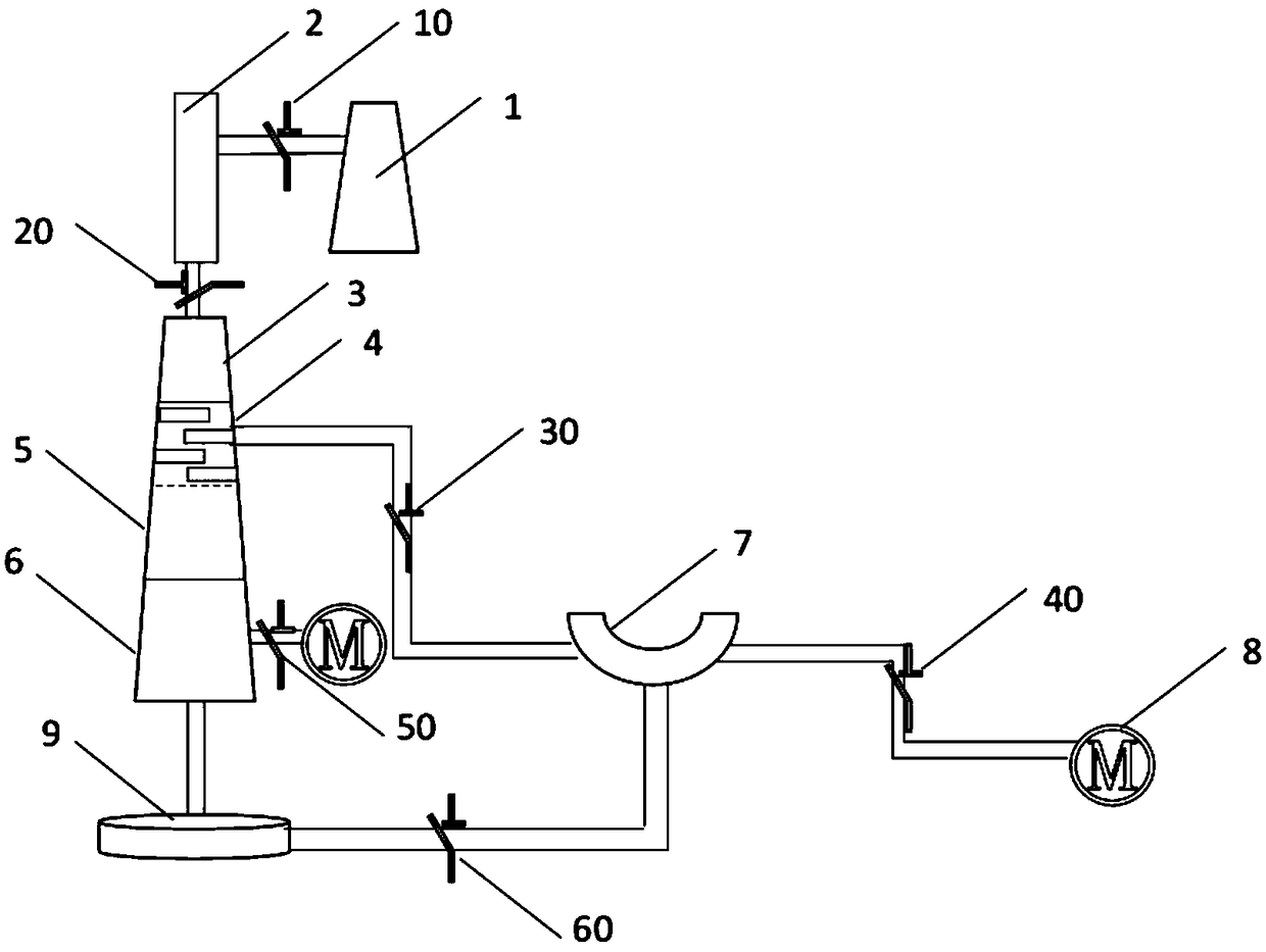
[0039] A desulfurization device, such as figure 1 As shown, the device includes a chimney 1 for discharging waste gas containing sulfide, and the chimney is communicated with an integral series heat exchanger 2 through a first damper 10, and the heat exchanger 2 is communicated with a desulfurization tower In order to pass the cooled waste gas into the dust removal chamber 3 in the desulfurization tower, the heat exchanger 2 and the dust removal chamber 3 can be communicated through a second damper 20;

[0040] The desulfurization tower is respectively provided with a dust removal chamber 3, an atomization spray chamber 4, a sulfide absorption chamber 5, and a waste water collection chamber 6 from top to bottom, and the dust removal chamber 3, atomization spray chamber 4, and sulfide absorption chamber 5 and the waste water collection chamber 6 are connected successively, and the waste water collection chamber 6 is communicated with the circulating water device; the waste wate...

Embodiment 2

[0055] A desulfurization device, such as figure 1 As shown, the device includes a chimney 1 for discharging waste gas containing sulfide, and the chimney is communicated with an integral series heat exchanger 2 through a first damper 10, and the heat exchanger 2 is communicated with a desulfurization tower In order to pass the cooled waste gas into the dust removal chamber 3 in the desulfurization tower, the heat exchanger 2 and the dust removal chamber 3 can be communicated through a second damper 20;

[0056] The desulfurization tower is respectively provided with a dust removal chamber 3, an atomization spray chamber 4, a sulfide absorption chamber 5, and a waste water collection chamber 6 from top to bottom, and the dust removal chamber 3, atomization spray chamber 4, and sulfide absorption chamber 5 and the waste water collection chamber 6 are connected successively, and the waste water collection chamber 6 is communicated with the circulating water device; the waste wate...


PUM


Abstract

The invention discloses a desulfurization device. A dust removal chamber, an atomizing and spraying chamber, a sulfide absorbing chamber and a wastewater collecting chamber are arranged in the desulfurization tower from top to bottom separately; the dust removal chamber, the atomizing and spraying chamber, the sulfide absorbing chamber and the wastewater collecting chamber are sequentially in communication; the wastewater collecting chamber is communicated with a circulating water device; the device is further equipped with a circulating water device; the circulating water device comprises a circulating water extracting device; the circulating water extracting device is communicated with a circulating water condensing device; a water pump is communicated with the atomizing and spraying chamber through a plurality of water draining tubes; a first water draining valve is arranged on each water draining tube; an electrostatic dust remover is arranged in the dust removal chamber; and theair filter and the electrostatic dust remover are mounted inside the dust removal chamber. The dust removal chamber is arranged, so that particles such as dust contained in smoke gas can be efficiently removed.

Description

technical field [0001] The invention belongs to the field of environmental protection machinery, in particular to an exhaust gas desulfurization system. Background technique [0002] The flue gas emitted by coking plants and brick factories contains a large amount of sulfur dioxide, which is very harmful to the human body and the environment, and is currently the main source of pm2.5. [0003] At present, there are generally three desulfurization methods: pre-combustion, in-combustion and post-combustion desulfurization. With the development of industry and the improvement of people's living standards, the thirst for energy is also increasing, SO in coal-fired flue gas 2 It has become the main cause of air pollution. Reduce SO 2 Pollution has become the top priority of today's atmospheric environment governance. Many flue gas desulfurization processes have been widely used in industry, and it also has important practical significance for the treatment of exhaust gas from...

Claims


Application Information

Patent Timeline
Patent Type & Authority Applications(China)
IPC IPC(8): B01D53/78B01D53/48B01D50/00
CPCB01D50/00B01D53/48B01D53/78B01D53/96B03C3/017
Inventor 丁武轩
Owner 丁武轩
Why Eureka
Try Eureka