Cleaning equipment for bottom of vehicle

A technology for cleaning equipment and vehicles, applied in the field of vehicle cleaning, to achieve the effect of simplifying procedures, offsetting damage, and good decontamination effect

Active Publication Date: 2018-09-14
中国人民解放军军事科学院防化研究院 +1
View PDF5 Cites 2 Cited by
  • Summary
  • Abstract
  • Description
  • Claims
  • Application Information

AI Technical Summary

Problems solved by technology

[0007] The technical effect of this scheme is: through the cooperation of the driving mechanism and the track, the spraying vehicle reciprocates on the track while the vehicle remains stationary, and at the same time, with the cooperation of the decontamination pipe and the nozzle, the bottom of the vehicle is repeatedly cleaned and disinfected, The decontamination effect is very good, and by distributing the decontamination pipes on both sides of the track, the sprayer does not need to coil the decontamination pipes during the reciprocating motion, which simplifies the procedure. At the same time, the decontamination pipes run according to the established route to ensure that the decontamination pipes There will be no entanglement problem in a small space, and the vehicle can be cleaned and disinfected smoothly; among them, the output shaft of the DC motor transmits the rotational motion to the driving wheel through the chain, which can effectively offset the tension of the traction rope on the output shaft of the DC motor. At the same time, when the driving mechanism drives the spraying vehicle to move, the first gear drives the decontamination tube away from the end of the spraying vehicle to move through friction, wherein the moving direction of the decontamination tube is opposite to that of the spraying vehicle, so that the cleaning The timely retraction of the disinfection pipe effectively overcomes the problem that the vehicle cannot be decontaminated due to the narrow decontamination site

Method used


Image

  • Cleaning equipment for bottom of vehicle
  • Cleaning equipment for bottom of vehicle
  • Cleaning equipment for bottom of vehicle

Examples


Embodiment Construction

[0019] Further detailed explanation through specific implementation mode below:

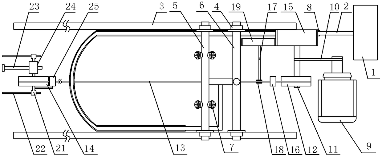
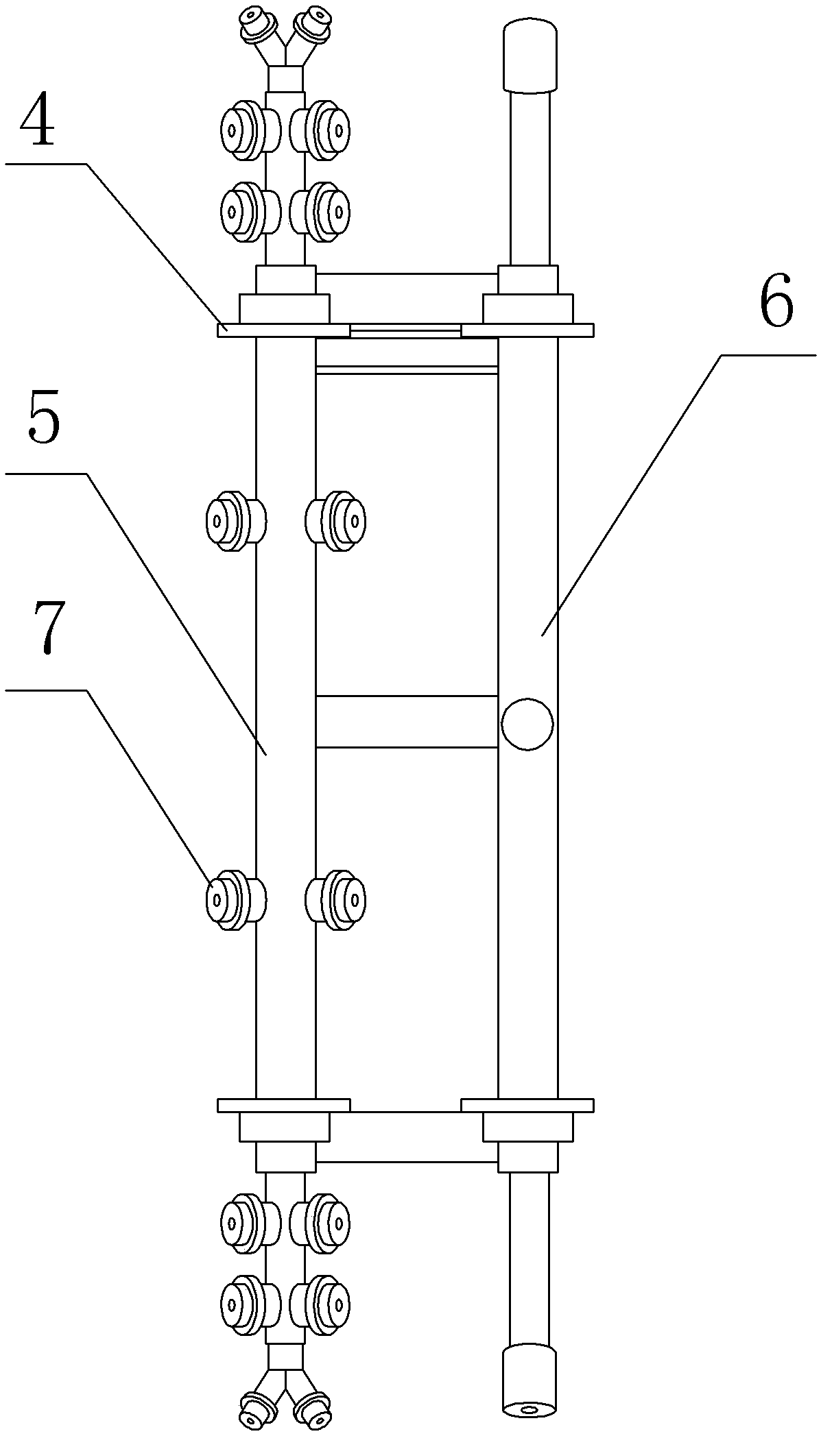
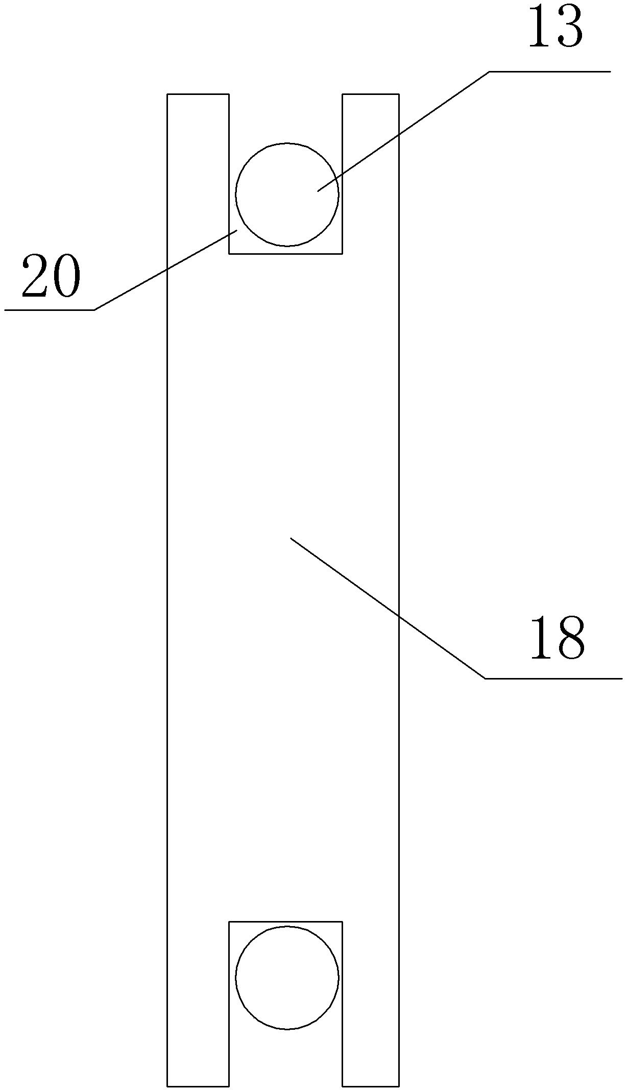
[0020] The reference signs in the drawings of the description include: decontamination tank 1, decontamination pipe 2, track 3, spray vehicle 4, cleaning pipe 5, disinfection pipe 6, nozzle 7, one-way drag chain 8, waterproof DC motor 9, chain 10. Rotating shaft 11, driving wheel 12, wire rope 13, driven wheel 14, first gear 15, guide wheel 16, detection rod 17, detection block 18, second gear 19, bayonet 20, support shaft 21, optical axis 22 , screw rod 23, nut 24, guide block 25, arc groove 26.

[0021] Such as figure 1 The shown cleaning equipment for the bottom of the vehicle includes a decontamination tank 1, a decontamination pipe 2, a driving mechanism, a detection mechanism, a track 3, a spraying vehicle 4 and a tensioning mechanism. The guide rail is composed of four guide rail components, and the guide rail components are spliced ​​by bolts, which can greatly improve the convenience o...


PUM


Abstract

The invention relates to the field of vehicle cleaning, in particular to cleaning equipment for the bottom of a vehicle. The cleaning equipment comprises a rail, a scrubbing pipe, a spraying vehicle and a driving mechanism; one end of the scrubbing pipe is communicated with a scrubbing pool, and the other end of the scrubbing pipe extends to the other side of the rail along one side of the rail; the other end of the scrubbing pipe is communicated with a nozzle; the driving mechanism comprises a direct-current motor, a chain, a driving wheel, a traction rope, a driven wheel and a first gear; the driving wheel is connected with an output shaft of the direct-current motor through the chain, the driven wheel is connected with the driving wheel through the traction rope, and the traction rope is fixedly connected with the spraying vehicle; the first gear is coaxially connected with the driving roller, the first gear is in contact with one end of the scrubbing pipe, and the moving directionof the scrubbing pipe conveyed by the first gear is opposite to the moving direction of the spraying vehicle. When the technical scheme is used, the scrubbing pipe cannot be twisted in the follow-up process in a narrow space, and meanwhile the problem about scrubbing the vehicle in a narrow scrubbing place is effectively solved.

Description

technical field [0001] The invention relates to the field of vehicle cleaning, in particular to cleaning equipment for vehicle bottoms. Background technique [0002] For a long time, the disinfection of the vehicle body is a subject of great concern. Especially in special environments such as earthquake relief, nuclear chemical rescue, customs, hospitals, and aquaculture, the requirements for vehicle disinfection are higher. In the past, the chemical disinfectant was prepared in the decontamination tank, so that the vehicle tires were disinfected when the vehicle passed through the decontamination tank. In addition, a manual sprayer was equipped to spray the agent on the outside of the vehicle. Since the chemical disinfectant in the decontamination tank is easy to be polluted, this time This disinfection method is difficult to ensure the disinfection effect of the bottom of the vehicle. [0003] In order to improve the cleaning and disinfection effect of the bottom of the ...

Claims


Application Information

Patent Timeline
Patent Type & Authority Applications(China)
IPC IPC(8): B60S3/04
CPCB60S3/04
Inventor 李国荣廖洋陈尚志谯远朱安娜王志甄周睿程煜寒谢邱黎郭庆
Owner 中国人民解放军军事科学院防化研究院
Why Eureka
Try Eureka