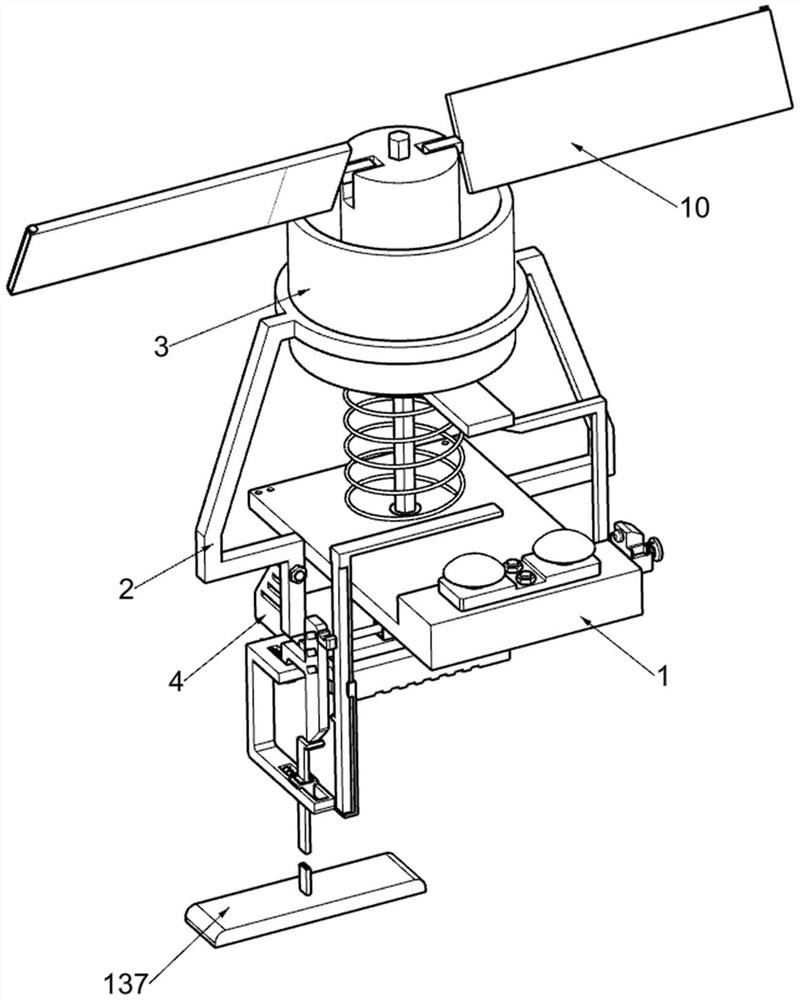
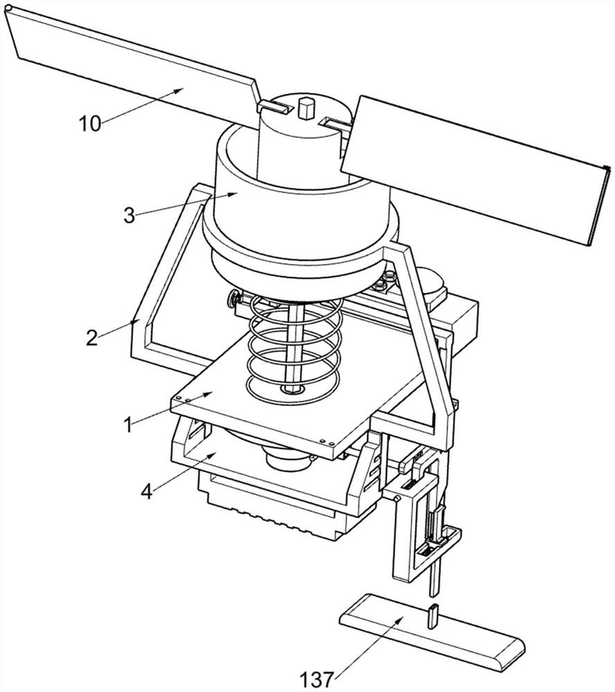
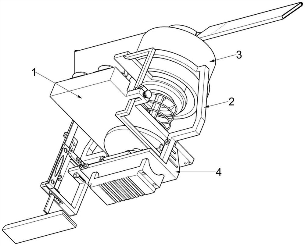
Offshore wind driven generator capable of retracting blades according to wind strength
A technology for wind turbines and generators, which is applied to wind turbines, wind turbine control, and wind power generation, etc., can solve the problems of low power generation efficiency and blade damage of generators, and achieve the effect of improving power generation efficiency and prolonging service life.
- Summary
- Abstract
- Description
- Claims
- Application Information
AI Technical Summary
Problems solved by technology
Method used
Image
Examples
Embodiment 1
[0048] An offshore wind turbine that retracts the blades according to the strength of the wind, such as Figure 1-10As shown, it includes a base plate 1, a support frame 2, a cylinder limit ring 3, a support plate 4, a rotating shaft 5, a generator 6, a movable transmission part 7, a push-off part 8, a support block 9, and a blade 10 And the torsion spring 11, the support frame 2 is fixedly connected to the base plate 1, the upper part of the support frame 2 adopts a ring structure, and the cylinder limit ring 3 is fixedly installed on the support frame 2, and the cylinder limit ring 3 is cylindrical , the support frame 2 is connected with a support plate 4 by bolts, the base plate 1 and the support plate 4 are connected with a rotating shaft 5 in a common rotation type, and the bottom end of the rotating shaft 5 is connected with a generator 6, and the generator 6 and the support plate 4 Fixedly connected, the base plate 1 is provided with a movable transmission part 7, the m...
Embodiment 2
[0053] On the basis of Example 1, such as Figure 11-14 As shown, it also includes an adjustment part 12, which is used to make the movable transmission part 7 retract the blade 10 according to the wind strength. The adjustment part 12 is arranged on the top of the support plate 4. , cylinder 123, piston plate 124, return spring 125, connecting frame 126, guide plate 127 and L-shaped push plate 128, support plate 4 tops are fixedly connected with column 121, and column 121 is cylindrical, and column 121 rotates with rotating shaft 5 Inflatable compression cushion 122 is fixedly installed on the outside of the column 121, and a cylinder 123 is fixedly connected to the top of the support plate 4. The interior of the cylinder 123 is a hollow structure, and the cylinder 123 communicates with the inflatable compression cushion 122. Plate 124, piston plate 124 is rectangular, is connected with the return spring 125 that is used to drive piston plate 124 to reset between piston plate...
Embodiment 3
[0058] On the basis of Example 2, such as Figure 15 As shown, a warning part 14 is also included, and the warning part 14 for reminding the staff to maintain the equipment is arranged on the top of the base plate 1. The warning part 14 includes a fixed plate 141, an alarm bell 142 and a switch 143, basically The top of the seat plate 1 is connected with a fixed plate 141 by bolts, the fixed plate 141 is symmetrically connected with an alarm bell 142 , and the top of the base plate 1 is provided with a switch 143 for controlling the operation of the alarm bell 142 .
[0059] When the support bar 85 moves due to the increased wind force, the support bar 85 will press the switch 143 and make the alarm bell 142 operate, thereby the effect of warning can be played to the staff. When the support bar 85 resets, it will no longer press the switch 143, The alarm bell 142 then stops operating, which is convenient for the staff to carry out maintenance work on the equipment.
PUM
 Abstract
Description
Claims
Application Information
 - R&D
- Intellectual Property
- Life Sciences
- Materials
- Tech Scout
- Unparalleled Data Quality
- Higher Quality Content
- 60% Fewer Hallucinations
Browse by: Latest US Patents, China's latest patents, Technical Efficacy Thesaurus, Application Domain, Technology Topic, Popular Technical Reports.
© 2025 PatSnap. All rights reserved.Legal|Privacy policy|Modern Slavery Act Transparency Statement|Sitemap|About US| Contact US: help@patsnap.com


