Energy-saving waterproof LED intelligent point control lamp string
An LED light bulb and point control technology, which is applied in energy-saving control technology, lampshade, components of lighting devices, etc., can solve the problem that LED light bulbs are easily wetted by rain, cannot intelligently change the brightness of LED light bulbs, and cannot effectively reduce power consumption, etc. problem, to achieve the effect of enhancing the display effect, facilitating adjustment, and avoiding short circuits
- Summary
- Abstract
- Description
- Claims
- Application Information
AI Technical Summary
Problems solved by technology
Method used
Image
Examples
Embodiment 1
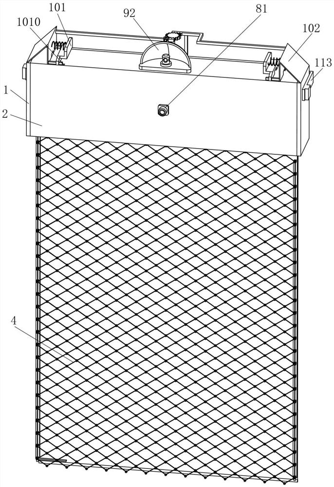
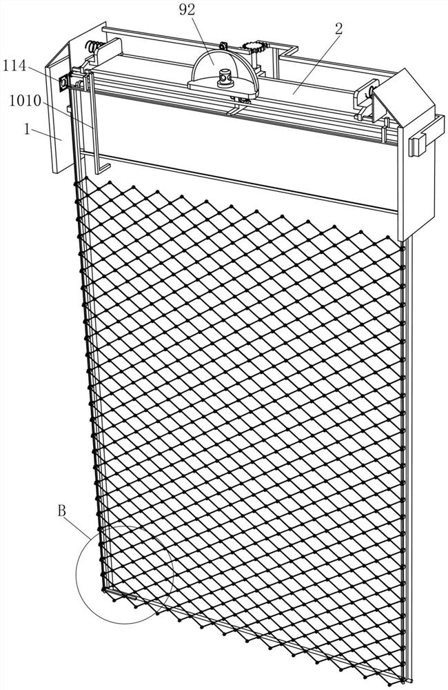
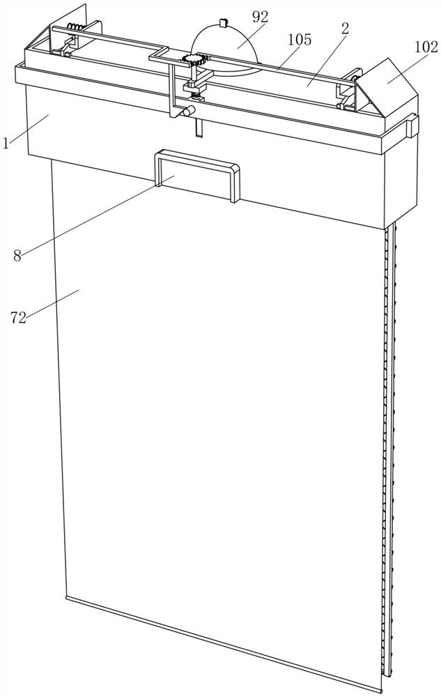
[0045] An energy-saving and waterproof LED intelligent point-controlled light string, such as figure 1 , figure 2 , image 3 , Figure 4 , Figure 5 , Figure 6 , Figure 7 , Figure 8 and Figure 9 As shown, it includes a U-shaped frame 1, an L-shaped cover plate 2, a retractable part 3, a mesh wire 4, an LED bulb 5, a strip electromagnet 6, a reflective part 7, and a first humidity sensor 81. The U-shaped frame 1 The front side is fixed with an L-shaped cover plate 2, and the U-shaped frame 1 is provided with a retractable part 3 for waterproofing. The retractable part 3 is provided with an LED bulb 5, and the LED bulb 5 emits light for displaying patterns, numbers or providing lighting , the LED bulbs 5 are jointly fixedly connected with mesh wires 4, and the other intersection points on the mesh wires 4 are also fixedly connected with LED bulbs 5, and strip electromagnets 6 are fixedly connected on the inner walls of the left and right sides of the U-shaped frame 1...
Embodiment 2
[0051] On the basis of Example 1, such as Figure 10 As shown, it also includes an intelligent light intensity adjustment part 9, which is arranged on the top of the U-shaped frame 1, and the light intensity intelligent adjustment part 9 includes a pillar 91, a reflector 92 and a photoelectric sensor 93, and the U-shaped frame 1 The top is rotatably connected with a pillar 91, and the lower part of the pillar 91 is fixedly connected with a reflector 92 for collecting light on the front side of the device. The reflector 92 is fixed with a photoelectric sensor 93 inside, and the photoelectric sensor 93 is used to sense the light on the front side of the device.
[0052] The reflector 92 will collect the light located on the front side of the device, and the photoelectric sensor 93 is used to sense the light on the front side of the device. During the day, the brightness of the external environment is brighter, and the photoelectric sensor 93 senses the light intensity and transmi...
Embodiment 3
[0054] On the basis of Example 2, such as Figure 11 , Figure 12 and Figure 14 As shown, a detection orientation adjustment part 10 is also included, and the detection orientation adjustment part 10 for making the reflector 92 receive light in multiple directions is arranged on the U-shaped frame 1. Movable plate 102, return spring 103, first rack bar 104, second rack bar 105, meshing gear 106, block electromagnet 107, permanent magnet 108, push bar 109 and L-shaped clamping bar 1010, U-shaped frame 1 The support plate frame 101 is symmetrically fixed on the top, and the support plate frame 101 is slidably connected with an inclined movable plate 102. Back-moving spring 103, the first rack bar 104 is affixed to the left part of the inclined-plane movable plate 102 positioned on the right side, the second rack bar 105 is affixed to the right part of the inclined-plane movable plate 102 positioned on the left side, and the top of the pillar 91 is affixed to a rack bar 105. ...
PUM
 Abstract
Description
Claims
Application Information
 - R&D
- Intellectual Property
- Life Sciences
- Materials
- Tech Scout
- Unparalleled Data Quality
- Higher Quality Content
- 60% Fewer Hallucinations
Browse by: Latest US Patents, China's latest patents, Technical Efficacy Thesaurus, Application Domain, Technology Topic, Popular Technical Reports.
© 2025 PatSnap. All rights reserved.Legal|Privacy policy|Modern Slavery Act Transparency Statement|Sitemap|About US| Contact US: help@patsnap.com


