
An electrospinning device

An electrospinning and equipment technology, applied in the field of electrospinning equipment, can solve the problems of difficult fiber collection, low effective productivity, and low collection efficiency, and achieve the effects of uniform spinning, improved film quality, and easy disassembly

Active Publication Date: 2021-08-31
MEDPRIN REGENERATIVE MEDICAL TECH
View PDF8 Cites 0 Cited by
  • Summary
  • Abstract
  • Description
  • Claims
  • Application Information

AI Technical Summary

Problems solved by technology

[0005] Although the electrospinning equipment of the rotary roller type has been successfully industrialized, due to the specificity of the electrospinning technology, the collection efficiency is relatively low
Specifically, fiber collection becomes more and more difficult as charge builds up on the surface of the receiving roll and the surrounding potential is lower, generally during roll receiving.
According to actual industrialization data statistics, in the case of roller receiving, the receiving rate is only 40% to 60% (calculated according to the weight / feeding amount of the fiber film on the receiving roller), and its effective productivity is relatively low
The defects of other receiving methods are also more prominent. For example, the thickness of flat plate receiving decreases from the middle to the surrounding to form a circle. The diameter of the circle depends on the receiving distance. Because of the large difference in thickness, the usable area is not large; , The effect of parallel electrode reception is the same as that of a flat plate; the flywheel receives the linear fiber strips obtained under normal circumstances, and the efficiency is not high

Method used


Image

  • An electrospinning device
  • An electrospinning device
  • An electrospinning device

Examples


Embodiment 1

[0041] 1) Prepare a liquid dispenser with a diameter of 4 cm and a double-layer structure liquid dispenser with a sleeve diameter of 8 cm. The liquid dispenser is provided with a plurality of needles, and the needles are fixed on the liquid pipe and pass through the surface of the sleeve. The needles are distributed in a ring on the surface of the liquid pipe and the sleeve. Eight needles are distributed in a circumferential direction of the liquid pipe and the sleeve. The angle between two adjacent needles on the same ring is 45 degrees. The distance between the rings is 6cm, and the assembled liquid dispenser is installed on the second supporting device, wherein the second supporting device is a lifting platform. And connect the dispenser with the liquid pushing device and the high-voltage electrostatic generating device.

[0042] 2) Prepare a cylindrical receiver with an inner diameter (radius) of 30 cm, and install it on the first support device, which is also a rotating d...

Embodiment 2

[0054] 1) Prepare a liquid dispenser with a diameter of 6 cm and a sleeve diameter of 10 cm. The liquid dispenser is provided with a plurality of needles, and the needles are fixed on the liquid pipe and pass through the surface of the sleeve. The needles are distributed in a ring on the surface of the liquid pipe and the sleeve, and 6 needles are distributed in a circumferential direction of the liquid pipe and the sleeve, which are distributed in a ring. The angle between two adjacent needles on the same ring is 60 degrees. The ring spacing between the two rings is 6 cm, and the assembled liquid dispenser is installed on the second supporting device, wherein the second supporting device is a lifting platform. And connect the dispenser with the liquid pushing device and the high-voltage electrostatic generating device.

[0055] 2) Prepare a cylindrical receiving tube with an inner diameter (radius) of 36 cm, and install it on the first supporting device, which is also a rotat...


PUM

PropertyMeasurementUnit
diameteraaaaaaaaaa
diameteraaaaaaaaaa
diameteraaaaaaaaaa

Abstract

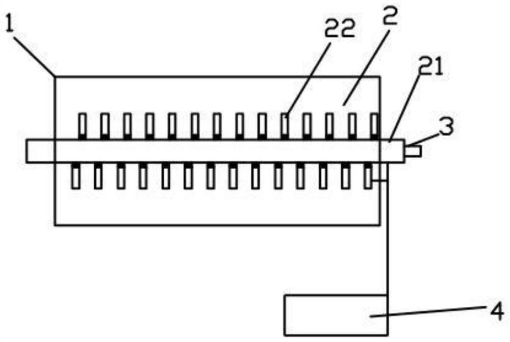
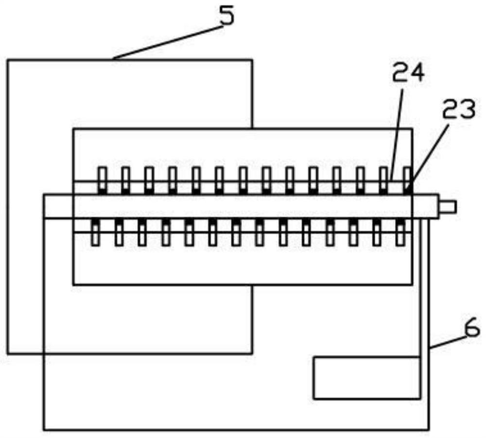
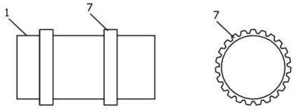
The invention relates to an electrospinning device, which includes a receiving cylinder, a liquid separator, a liquid pushing device, and a high-voltage electrostatic generating device; the receiving cylinder has a cylindrical structure with openings at both ends and a hollow interior, and The receiving cylinder is arranged in a horizontal direction; the liquid dispenser is arranged inside the receiving cylinder, and the liquid dispenser includes a liquid pipe and a needle, and the liquid pipe and the receiving cylinder are arranged concentrically, and the needle Set on the dispensing tube, the needle is in communication with the cavity of the dispensing tube; one end of the dispensing tube is sealed and the other end is open, and the opening end of the dispensing tube is connected to the liquid pushing device, and the high-voltage electrostatic generating device is connected to the liquid dispensing device. The needle connection provides the required high-voltage electric field for electrospinning. The electrospinning equipment of the present invention greatly improves the spinning efficiency and acceptance rate of the electrospinning equipment through the structural design of the receiving cylinder and the liquid separator, and can make the spinning more uniform and improve the film quality; at the same time, the equipment Easy to disassemble, convenient to adjust, good adaptability.

Description

technical field [0001] The present invention relates to the technical field of electrospinning, and more specifically, to an electrospinning device. Background technique [0002] Since Formhals invented the electrospinning technology in 1930, various polymer nanofibers have been successfully prepared and their properties have been studied in detail. The basic principle of electrospinning technology is as follows: In a high-voltage electrostatic field, the polymer solution enters and is charged at a high field strength, and the charged droplets are affected by Coulomb force, surface tension and the viscosity between the solutions. When in equilibrium, the appearance of the droplet appears as a Taylor cone; when the Coulomb force continues to increase, the force balance of the droplet is broken, and the fibers are pulled out from the droplet and continuously split into nanofibers in the process of moving to the collection end , the solution in the nanofibers volatilizes durin...

Claims


Application Information

Patent Timeline
Patent Type & Authority Patents(China)
IPC IPC(8): D01D5/00
CPCD01D5/0061D01D5/0069D01D5/0076
Inventor 詹泽丰邓坤学袁玉宇
Owner MEDPRIN REGENERATIVE MEDICAL TECH
Learn More