Polymer solution electrostatic spinning component, device and method
A technology of polymer solution and spinning assembly, applied in textile and papermaking, filament/thread forming, fiber processing, etc., can solve the problems of low spinning efficiency and too small spinning area, and improve spinning efficiency Effect
- Summary
- Abstract
- Description
- Claims
- Application Information
AI Technical Summary
Problems solved by technology
Method used
Image
Examples
Embodiment 1
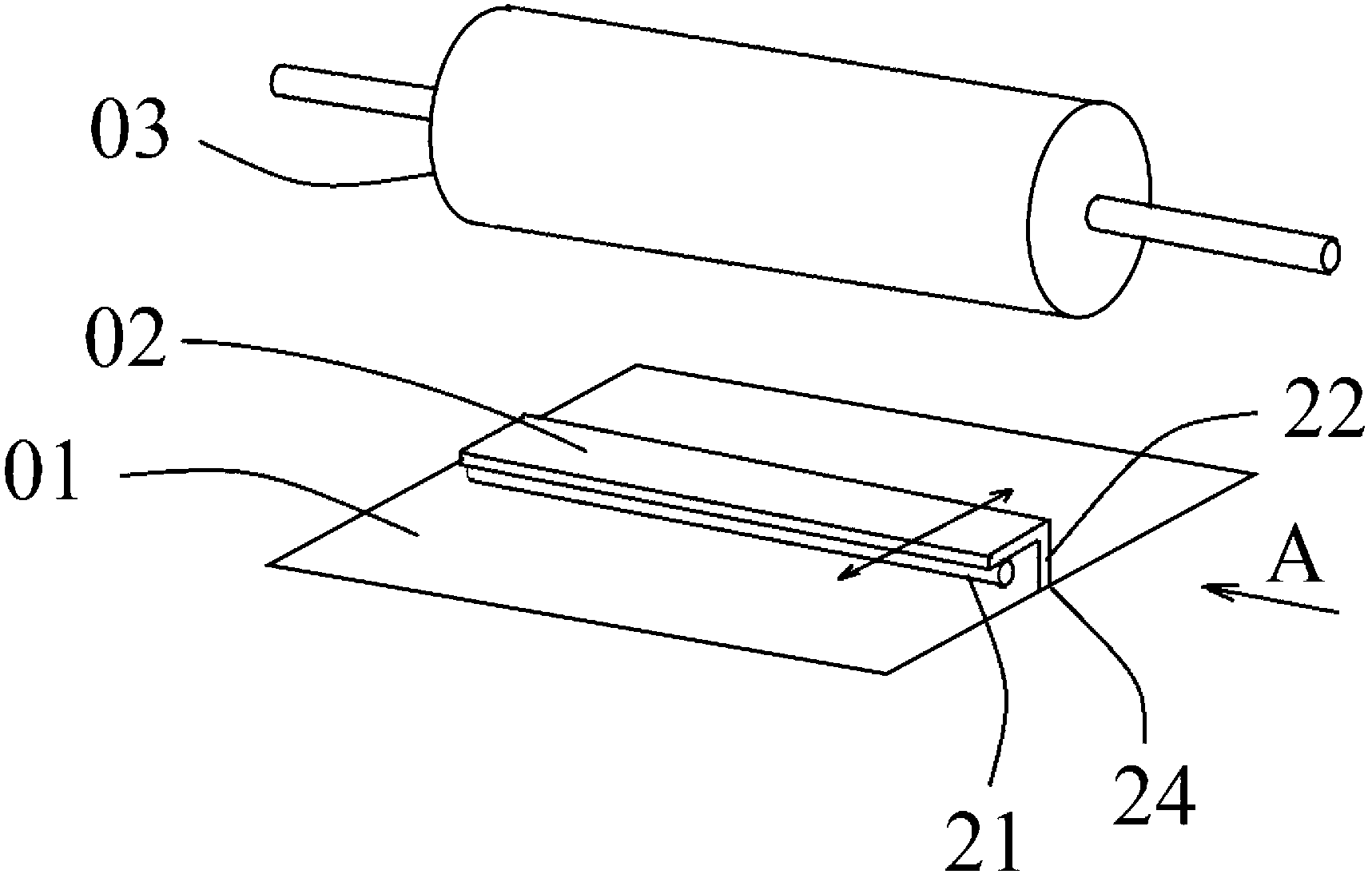
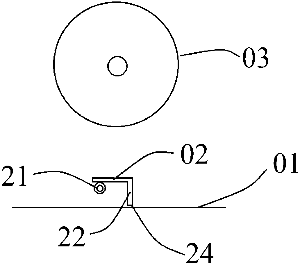
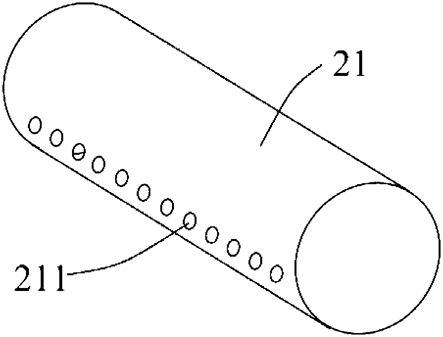
[0045]The structure of the polymer solution electrospinning assembly in Example 1 of the present invention will be described in detail with reference to FIG. 1 (1). As shown in Figure 1 (1), the polymer solution electrospinning assembly includes a first electrode 01, a second electrode 03 placed opposite to the first electrode 01, and a second electrode 03 located between the first electrode 01 and the second electrode. Spray mechanism 02 between electrodes 03. Wherein, the spraying mechanism 02 is used to spray the polymer solution on the surface of the first electrode 01. In order to have a larger spinning area for polymer solution electrospinning, this embodiment limits the first electrode 01 to be a flat plate electrode. The shape of the second electrode 03 is not limited, and it may be a cylindrical electrode, a flat plate electrode, or an electrode of other shapes. As long as an electrostatic field can be formed between the first electrode 01 and the second electrode 03...
Embodiment 2
[0057] Figure 6 It is a schematic structural diagram of the spinning assembly of Example 2 of the present invention. This spinning assembly has many similarities with the spinning assembly of Example 1. For the sake of brevity, this embodiment only focuses on the differences. Parts that are the same as those in Embodiment 1 will not be described in detail. For detailed description, please refer to Embodiment 1.
[0058] see Figure 6 , compared with Embodiment 1, the spraying mechanism 02 of the spinning assembly of this embodiment also includes a scraper 23 arranged parallel to the nozzle 21, and the scraper 23 and the flat plate 22 are respectively located on both sides of the nozzle, in other words , the nozzle 21 is located between the flat plate 22 and the scraper 23 . The scraper 23 can remove the solution remaining in the previous spinning cycle, avoiding the mixing of the sprayed new solution and the old solution, and will not cause the aging of the new solution. Co...
Embodiment 3
[0061] Figure 7 It is the schematic diagram of the spinning device of the third embodiment of the present invention. The spinning device includes a first electrode 01, a second electrode 03, a spraying mechanism 02, a high voltage power supply 04, a fiber collecting part 05, a liquid storage container 06, and a communication part 07 connecting the liquid storage container 06 and the spraying mechanism 02. Wherein, the first electrode 01 , the second electrode 03 and the spraying mechanism 02 constitute a spinning assembly, and the structure of the spinning assembly adopts the structure of the spinning assembly provided in Embodiment 1 or Embodiment 2.
[0062] During spinning, the first electrode 01 and the second electrode 03 are respectively connected to the positive and negative poles of the high-voltage power supply 04, or the first electrode 01 is connected to one of the electrodes of the high-voltage power supply and the second electrode 03 is grounded, so that the firs...
PUM
| Property | Measurement | Unit |
|---|---|---|
| size | aaaaa | aaaaa |
| diameter | aaaaa | aaaaa |
| diameter | aaaaa | aaaaa |
Abstract
Description
Claims
Application Information
 - R&D
- Intellectual Property
- Life Sciences
- Materials
- Tech Scout
- Unparalleled Data Quality
- Higher Quality Content
- 60% Fewer Hallucinations
Browse by: Latest US Patents, China's latest patents, Technical Efficacy Thesaurus, Application Domain, Technology Topic, Popular Technical Reports.
© 2025 PatSnap. All rights reserved.Legal|Privacy policy|Modern Slavery Act Transparency Statement|Sitemap|About US| Contact US: help@patsnap.com


