A coiled tubing string hydraulic breaking device

A pipe string and hydraulic technology, applied in the field of coiled tubing string hydraulic fracture device, can solve problems such as shear pin failure and chuck fracture

Inactive Publication Date: 2019-07-30
NORTHEAST GASOLINEEUM UNIV
View PDF11 Cites 0 Cited by
  • Summary
  • Abstract
  • Description
  • Claims
  • Application Information

AI Technical Summary

Problems solved by technology

[0007] The object of the present invention is to provide a coiled tubing string hydraulic fracturing device, which is used to solve the problem that the shear pins of the coiled tubing disconnecting device in the prior art are prone to premature failure, and the The chuck often breaks during the process

Method used


Image

  • A coiled tubing string hydraulic breaking device
  • A coiled tubing string hydraulic breaking device
  • A coiled tubing string hydraulic breaking device

Examples


Embodiment Construction

[0031] Below in conjunction with accompanying drawing, the present invention will be further described:

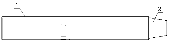
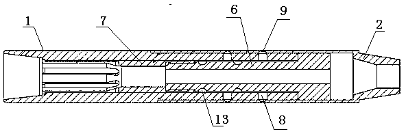
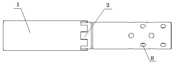
[0032] combine Figure 1-Figure 9 As shown, this coiled tubing string hydraulic fracturing device includes an upper tubing string 1, a lower joint 2, a supporting piston 6, and a collet 7. Refer to image 3 , Figure 4 , the outer wall of the upper column 1 has a seal groove 5, the spline groove 3 on the outer wall of the upper column 1 is located above the seal groove 5, and the lower end of the upper column 1 is provided with a plurality of channels 8, and two adjacent rows of channels 8 are arranged alternately, each A ball is arranged in the tunnel 8; refer to Figure 5 , Figure 6 , the upper port of the lower joint 2 is provided with a spline 4, the inner wall of the lower joint 2 is provided with a recess 9, the part below the sealing groove 5 of the upper pipe string 1 is inserted into the lower joint 2, the channel 8 of the upper pipe string 1 is connected with...


PUM


Abstract

The invention relates to a coiled tubing tubular column hydraulic breakage device. A plurality of hole channels are formed in the lower end of an upper tubular column, adjacent two lines of hole channels formed in an interlacing mode and a ball is arranged in each hole channel; concave holes are formed in the inner wall of a lower contact, the upper tubular column inserts into the lower contact and each hole channel of the upper tubular column corresponds to each concave hole of the lower contact in a one-to-one mode; the lower end of a chuck is connected with a supporting piston in a threading mode and the chunk and the supporting piston are located in the cavity formed by the upper tubular column and the lower contact; the chuck communicates with the supporting piston by respective center passageway; chuck jaws are arranged on the upper portion of the chuck, a clamping shoulder is formed at the upper end of each chuck jaw correspondingly and chunk jaws are clamped on a boss of the upper tubular column by the clamping shoulder; a piston shoulder of the supporting piston is clamped at the lower end opening of the upper tubular column; sliding grooves are formed in the external wallof the supporting piston and a pit is formed in each sliding groove correspondingly; when the piston shoulder moves to a circular bead of the upper tubular column, the pits of the sliding grooves correspond to hole channels of the upper tubular column in a one-to-one mode. A repeating shaking shock can be borne and is prevented from separating prematurely and the chuck is not out of operation prematurely.

Description

[0001] Technical field: [0002] The invention relates to downhole devices of oil and gas wells, in particular to a hydraulic fracturing device for coiled tubing strings. [0003] Background technique: [0004] During the drilling process, after the drilling is completed or the oil and gas production well is abandoned, in order to separate the unneeded coiled tubing in the lower part from the upper part, it is usually necessary to remove the tool or waste string from the coiled tubing string and leave it in the wellbore. During wellbore operations, tools may become stuck in the wellbore and the upper coiled tubing string needs to be removed so that fishing equipment can be re-entered in the wellbore to retrieve the stuck tool. Therefore, a coiled tubing disconnect device must be used. [0005] There are many kinds of disconnecting devices for coiled tubing, and the disconnecting devices of many tools use shear pins and collets to disconnect coiled tubing strings. Disadvantage...

Claims


Application Information

Patent Timeline
Patent Type & Authority Patents(China)
IPC IPC(8): E21B17/046E21B19/16
CPCE21B17/046E21B19/16
Inventor 候兆凯孙士慧李世昌冯金禹闫天雨逯广东
Owner NORTHEAST GASOLINEEUM UNIV
Why Eureka
Try Eureka