Power supply terminal and charging gun head

A power terminal and terminal technology, applied in circuits, electrical components, contact parts, etc., can solve problems such as difficulty in two-hand operation, reduce the insertion and extraction force of charging guns, etc., and achieve the effect of reducing labor intensity and reducing insertion and extraction force.

Active Publication Date: 2018-09-14
奕充机器人(苏州)有限公司
View PDF13 Cites 4 Cited by
  • Summary
  • Abstract
  • Description
  • Claims
  • Application Information

AI Technical Summary

Problems solved by technology

The development of fast charging technology makes the charging faster and faster, but due to the thickening of the cable and the power terminal of the charging gun, the plugging force of the charging gun head is also increasing. At present, it is difficult to operate with both hand...

Method used


Image

  • Power supply terminal and charging gun head
  • Power supply terminal and charging gun head
  • Power supply terminal and charging gun head

Examples


Embodiment 1

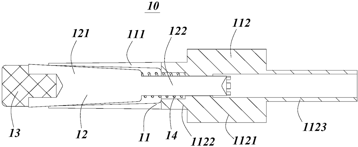
[0040] ginseng figure 1 As shown, the power terminal 10 in this embodiment includes a hollow terminal expansion tube 11, a terminal core rod 12 axially installed in the terminal expansion tube, an insulating head 13 fixedly installed on the end of the terminal core rod, and a terminal core rod fixed to the terminal. The elastic member 14 between the core rod and the terminal expansion tube.

[0041] Wherein, the terminal mandrel 12 includes an inserting portion 122 and a clamping portion 121, the terminal expansion tube 11 includes a mounting portion 112 and an expansion joint portion 111, the clamping portion 121 of the terminal core rod 12 and the expansion joint portion 111 of the terminal expansion tube 11 For coordinated installation, the insertion portion 122 of the terminal core rod 12 is fitted with the installation portion 112 of the terminal expansion tube 11 .

[0042] Specifically, in this embodiment, the cross-section of the clamping portion 121 of the terminal m...

Embodiment 2

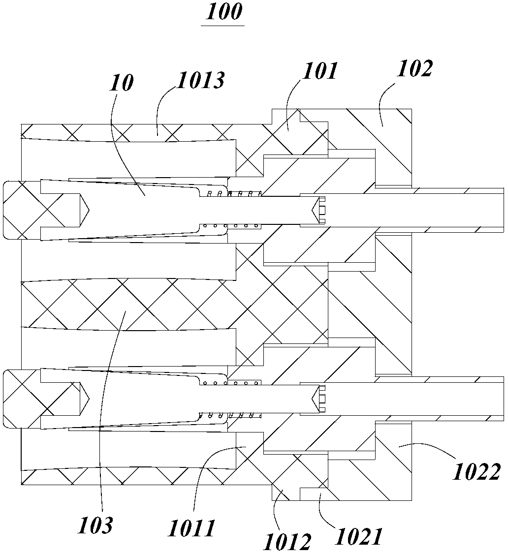
[0051] ginseng figure 2 As shown, the present embodiment discloses a charging gun head 100, which includes a plurality of power terminals 10, and a cover fixedly installed on the outside of the power terminals.

[0052] The power terminal 10 includes a hollow terminal expansion tube 11, a terminal core rod 12 axially installed in the terminal expansion tube, an insulating head 13 fixedly installed at the end of the terminal core rod, and a terminal core rod fixed between the terminal core rod and the terminal expansion tube. The specific structure of the elastic member 14 and the power terminal 10 is exactly the same as that in Embodiment 1, and will not be repeated here.

[0053] In this embodiment, the cover body includes a first cover body 101 and a second cover body 102 which are separated from each other. The first cover body 101 and the second cover body 102 are respectively provided with a number of limiting parts, through which the first cover body 101 and the second ...


PUM


Abstract

The present invention discloses a power supply terminal and a charging gun head. The power supply terminal comprises a hollow arranged terminal expand tube, a terminal core rod axially mounted in theterminal expand tube, an insulation head fixedly installed at the end portion of the terminal core rod and an elastic piece fixed between the terminal core rod and the terminal expand tube. The powersupply terminal comprises a first state when the elastic piece is compressed and a second state when the elastic is in normal state, and the length of the terminal core rod stretching into the terminal expand tube in the first state is larger than the length of the terminal core rod stretching into the terminal expand tube in the second state. The power supply terminal is arranged to reduce the plugging force of the charging gun head and relieve the labor intensity when plugging is performed; the terminal expand tube can reduce the friction prior to expansion of the terminal expand tube; and the terminal expand tube can ensure the contact pressure after the expansion of the terminal expand tube so as to ensure the heavy current conduction current effect.

Description

technical field [0001] The invention relates to the technical field of electric tool charging equipment, in particular to a power terminal and a charging gun head. Background technique [0002] With the rapid development of electric vehicles, electric vehicles are rapidly popularizing, and fast charging of electric vehicles has become the focus of the development of the automobile industry and the energy industry. The development of fast charging technology makes the charging faster and faster, but due to the thickening of the cable and the power terminal of the charging gun, the plugging force of the charging gun head is also increasing. At present, it is difficult to operate with both hands. The 50A DC charging gun is used as the For example, the maximum overall insertion force is 25KG, and the maximum insertion force of the DC terminal is 10.2KG. Therefore, reducing the insertion force of the charging gun is an urgent problem to be solved in the fast charging technology. ...

Claims


Application Information

Patent Timeline
IPC IPC(8): H01R13/02H01R13/502H01R13/516
CPCH01R13/02H01R13/502H01R13/516
Inventor 徐漫洋
Owner 奕充机器人(苏州)有限公司
Why Eureka
Try Eureka