Feeding conveying device for plate cutting machine

A conveying device and cutting machine technology, which is applied in the directions of conveyor objects, transportation and packaging, rollers, etc., can solve problems such as affecting the normal operation of the cutting machine, unfavorable feeding safety, and feeding height adjustment. Beneficial for maintenance and upkeep, avoid personal injury, avoid belt wear and tear

Inactive Publication Date: 2018-09-18
SUQIAN SUHUAN GLASS ARTS & CRAFTS
View PDF0 Cites 7 Cited by
  • Summary
  • Abstract
  • Description
  • Claims
  • Application Information

AI Technical Summary

Problems solved by technology

[0005] Aiming at the deficiencies of the prior art, the present invention provides a feeding and conveying device for a cutting machine, which solves the problem that the existing feeding and conveying device for a cutting machine is prone to wear or breakage, which seriously affects the cutting machine. The normal operation reduces the service life and poor stability, which is not conducive to the safety of feeding and the problem that the height of feeding cannot be adjusted

Method used

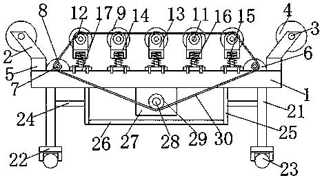
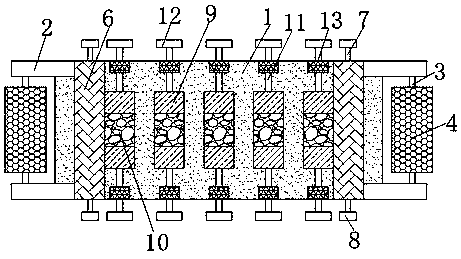
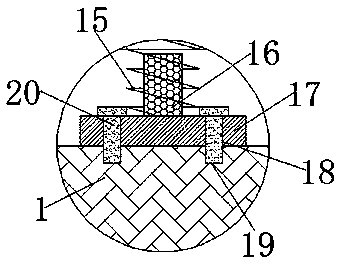

Image

  • Feeding conveying device for plate cutting machine
  • Feeding conveying device for plate cutting machine
  • Feeding conveying device for plate cutting machine

Examples


Embodiment Construction

[0022] The following will clearly and completely describe the technical solutions in the embodiments of the present invention with reference to the accompanying drawings in the embodiments of the present invention. Obviously, the described embodiments are only some, not all, embodiments of the present invention.

[0023] In describing the present invention, it is to be understood that the terms "center", "upper", "lower", "front", "rear", "left", "right", "vertical", "horizontal", The orientation or positional relationship indicated by "top", "bottom", "inner", "outer", "axial" and "radial" are based on the orientation or positional relationship shown in the drawings, and are only for the convenience of describing the The invention and the simplified description do not indicate or imply that the referred device must have a specific orientation, be constructed and operate in a specific orientation, and therefore should not be construed as limiting the present invention.

[0024...


PUM


Abstract

The invention discloses a feeding conveying device for a plate cutting machine and relates to the technical field of plate cutting machines. The feeding conveying device comprises a sending plate, andadjusting columns which are arranged in a vertically-symmetrical mode are mounted on the two sides of the sending plate correspondingly. A bearing rotary shaft is fixedly connected between the adjusting columns, and air cylinders are fixedly mounted at the bottom ends of the adjusting columns. The two sides, close to the air cylinders, of the sending plate are fixedly connected with auxiliary cylinder bases correspondingly, and driven shafts are fixedly mounted in the middles on the upper sides and the lower sides of the auxiliary cylinder bases correspondingly. Sending shaft rollers are arranged on the obverse side of the sending plate at equal intervals. According to the feeding conveying device for the plate cutting machine, the discharging and feeding heights can be adjusted advantageously, the discharging and feeding stability is improved effectively, abrasion caused by large-area direct contact with the sending shaft rollers is avoided, the service life is prolonged, the conveying efficiency is effectively improved, the friction coefficient can be increased, the feeding conveying safety is improved, and the damping property of the conveying device can be improved advantageously.

Description

technical field [0001] The invention relates to the technical field of board cutting machines, in particular to a feeding and conveying device for board cutting machines. Background technique [0002] In the prior art, the cutting machine, cabinet sawing machine, plate pressing machine and other types of machine tool equipment for plate production mostly use the transmission wheel to drive the transmission belt to drive the wood feed to drive the wood placed on the belt to realize processing. The surface of the board is relatively rough before finishing or grinding, so when the belt is used for transmission, the friction between the belt and the wood is very large. During the long-term work of the cutting machine, the belt is prone to wear or breakage. It seriously affects the normal operation of the cutting machine and reduces the service life. In addition, the stability of the feeding and conveying device of the existing cutting machine is poor, which is not conducive to t...

Claims


Application Information

Patent Timeline
Patent Type & Authority Applications(China)
IPC IPC(8): B65G13/07B65G13/12B65G39/02B65G39/14
CPCB65G13/07B65G13/12B65G39/02B65G39/14
Inventor 王玉梅
Owner SUQIAN SUHUAN GLASS ARTS & CRAFTS
Why Eureka
Try Eureka