Horizontal well hydraulic directional spraying gun

A horizontal well and hydraulic technology, applied in wellbore/well components, production fluids, earthwork drilling, etc., can solve the problems of high cost, low operation success rate, large impact, etc., and achieve low cost and high directional success rate. Effect

Active Publication Date: 2018-09-18
JEREH ENERGY SERVICES
View PDF5 Cites 112 Cited by
  • Summary
  • Abstract
  • Description
  • Claims
  • Application Information

AI Technical Summary

Problems solved by technology

Mechanical directional perforating tools install eccentric weights near the perforating parts, and rely on gravity to achieve spray gun orientation in the well. This method is greatly affected by the well environment and has a low success rate
Wireline directional perforation technology relies on gyroscopes to achieve in-hole orientation, which is extremely costly

Method used


Image

  • Horizontal well hydraulic directional spraying gun
  • Horizontal well hydraulic directional spraying gun
  • Horizontal well hydraulic directional spraying gun

Examples


Embodiment 1

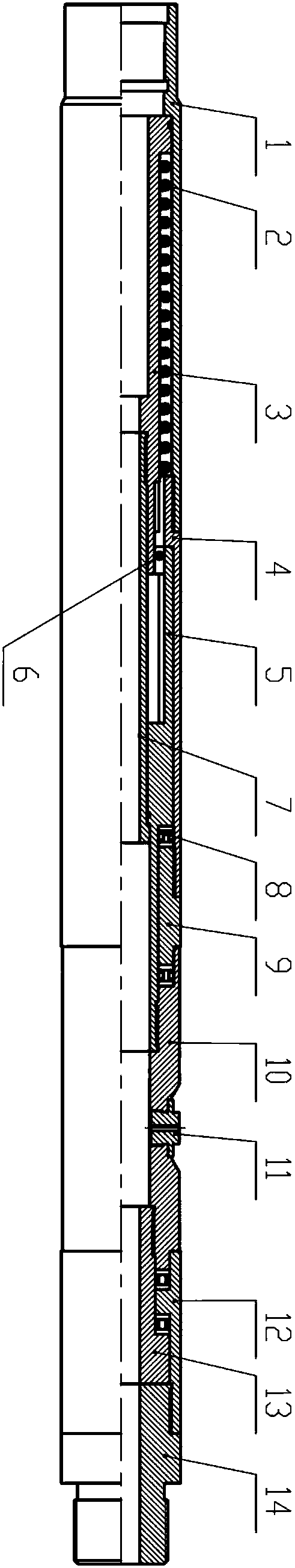
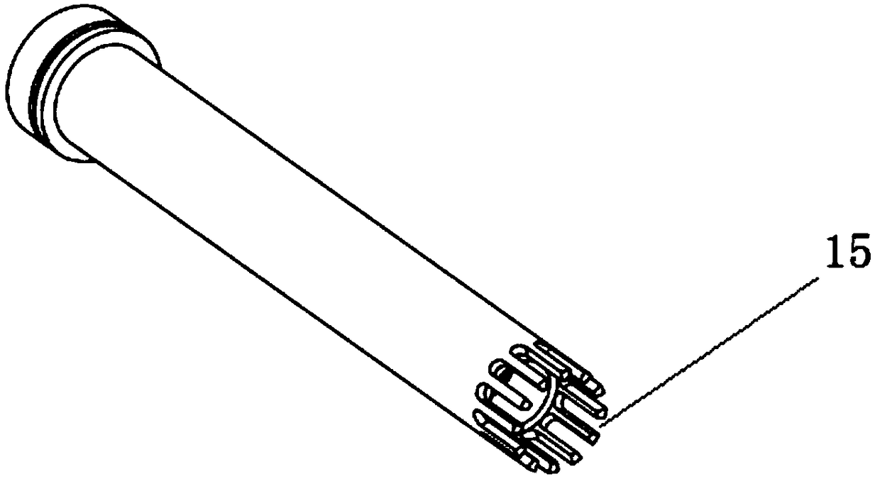
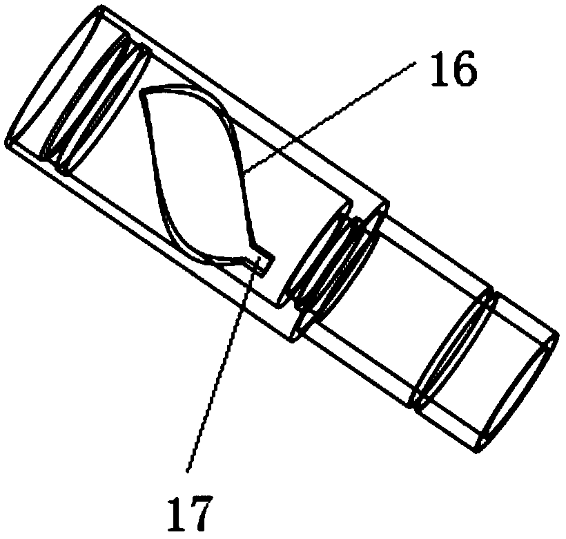
[0017] Such as Figure 1-3 As shown, a hydraulic directional spray gun for a horizontal well includes a directional split-tooth hydraulic cylinder 3, an envelope sleeve 5, a directional steel ball 6, a thrust bearing 8 and a nozzle 11, and the directional split-tooth hydraulic cylinder 3 is sleeved inside the upper joint 1, And form an annulus with the upper joint 1, a return spring 2 is arranged in the annulus, the right end of the upper joint 1 is connected with the upper shell 4, the inner part of the upper shell 4 is equipped with an envelope sleeve 5, and the center rod 7 passes through the envelope The sleeve 5 is internally connected to the internal thread at the right end of the directional split gear cylinder 3, and a closed space is formed between the upper shell 4, the directional split gear fluid cylinder 3 and the envelope sleeve 5, and the directional steel ball 6 is placed in the space, and the upper shell 4. The right end is threadedly connected with the connec...

Embodiment 2

[0021] A hydraulic directional spray gun for a horizontal well, comprising a directional split-tooth hydraulic cylinder 3, an envelope sleeve 5, a directional steel ball 6, a thrust bearing 8 and a nozzle 11, the directional split-tooth hydraulic cylinder 3 is sleeved inside the upper joint 1, and The joint 1 forms an annular space, and a return spring 2 is arranged in the annular space. The right end of the upper joint 1 is connected with the upper shell 4. The upper shell 4 is equipped with an envelope sleeve 5, and the central rod 7 passes through the envelope sleeve 5. Connected to the internal thread on the right end of the directional split gear cylinder 3, a closed space is formed between the upper casing 4, the directional split gear fluid cylinder 3 and the envelope sleeve 5, and the directional steel ball 6 is placed in this space, and the right end of the upper casing 4 is connected to the The connecting sleeve 9 is threaded, the two ends of the connecting sleeve 9 a...

Embodiment 3

[0025] A hydraulic directional spray gun for a horizontal well, comprising a directional split-tooth hydraulic cylinder 3, an envelope sleeve 5, a directional steel ball 6, a thrust bearing 8 and a nozzle 11, the directional split-tooth hydraulic cylinder 3 is sleeved inside the upper joint 1, and The joint 1 forms an annular space, and a return spring 2 is arranged in the annular space. The right end of the upper joint 1 is connected with the upper shell 4. The upper shell 4 is equipped with an envelope sleeve 5, and the central rod 7 passes through the envelope sleeve 5. Connected to the internal thread on the right end of the directional split gear cylinder 3, a closed space is formed between the upper casing 4, the directional split gear fluid cylinder 3 and the envelope sleeve 5, and the directional steel ball 6 is placed in this space, and the right end of the upper casing 4 is connected to the The connecting sleeve 9 is threaded, the two ends of the connecting sleeve 9 a...


PUM


Abstract

The invention relates to the technical field of oil and gas well production increase and fracturing operation, in particular to a horizontal well hydraulic directional spraying gun. The horizontal well hydraulic directional spraying gun comprises a directional split tooth cylinder, an enveloping line sleeve, a directional steel ball, thrust bearings and nozzles. The directional split tooth cylinder and an upper connector form an annular space, a reset spring is arranged in the annular space, the right end of the upper connector is connected with an upper housing, the enveloping line sleeve issleeved with the interior of the upper housing, a central rod penetrates through the interior of the enveloping line sleeve to be connected to an internal thread at the right end of the directional split tooth cylinder, and a closed space is defined by the upper housing, the directional split cylinder and the enveloping line sleeve; the directional steel ball is placed in the closed space, the right end of the upper housing is in threaded connection with a connecting sleeve, the thrust bearings are symmetrically disposed at both ends of the connecting sleeve, and the right end of the enveloping line sleeve is connected with a spraying gun casing. Forced orientation of the spraying gun casing can be achieved by a hydraulic driving mode, the orientation success rate is high, tools can be reused after maintenance and protection, and the cost is low.

Description

technical field [0001] The invention relates to the technical field of oil and gas well stimulation and fracturing operations, in particular to a hydraulic directional spray gun for a horizontal well. Background technique [0002] In recent years, stimulation operations have gradually become the most important operation content in oil and gas fields. Hydraulic perforation followed by hydraulic fracturing is the main form of fracturing. This operation can further expand the productivity of oil and gas wells and improve recovery. After years of operation verification, it is very reliable to increase production capacity through hydraulic perforation and fracturing stimulation operations, and the benefits are extremely high. However, some horizontal wells have uneven distribution of oil and gas in the vertical direction in the horizontal section, and there are water layers in some directions. Once the perforation leads to the water layer, the water layer will be communicated wi...

Claims


Application Information

Patent Timeline
Patent Type & Authority Applications(China)
IPC IPC(8): E21B43/118E21B43/26
CPCE21B43/118E21B43/26
Inventor 迟帅邱俊人程欢韩滔
Owner JEREH ENERGY SERVICES
Why Eureka
Try Eureka