CT energy-obtaining-based power transmission line deicing device

A transmission line and base technology, which is applied to the field of deicing devices for transmission lines based on CT energy extraction, can solve problems such as inconvenience in hanging and access, and increase the quality of transmission lines, so as to ensure stability, avoid damage and transmission line damage, and move flexible effects

Active Publication Date: 2018-09-18
国网河南省电力公司邓州市供电公司
View PDF13 Cites 12 Cited by
  • Summary
  • Abstract
  • Description
  • Claims
  • Application Information

AI Technical Summary

Problems solved by technology

Although the invention has a simple structure, it still adopts the suspension method, whic

Method used


Image

  • CT energy-obtaining-based power transmission line deicing device
  • CT energy-obtaining-based power transmission line deicing device
  • CT energy-obtaining-based power transmission line deicing device

Examples


Embodiment 1

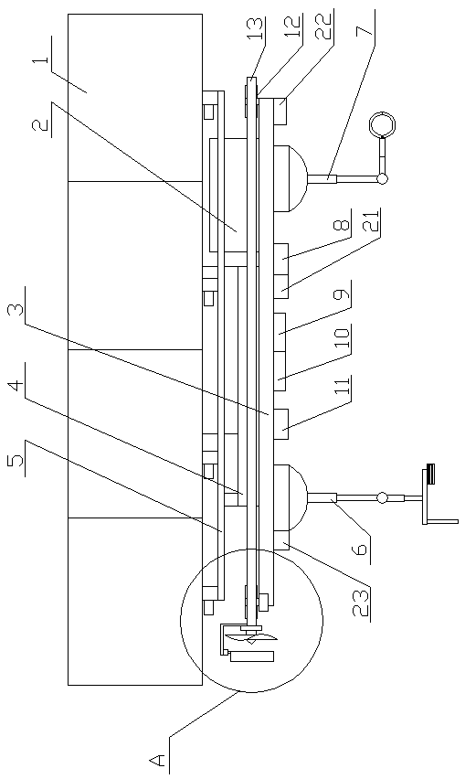
[0036] This embodiment provides a power transmission line de-icing device based on CT energy acquisition, including a de-icing base 3, a suspension mechanism set on the de-icing base 3, a suspension mechanism set on the de-icing base 3 The moving mechanism, the auxiliary support mechanism 7 arranged on the deicing base 3, the deicing mechanism 6 arranged on the deicing base 3, and the deicing mechanism 6 arranged on the deicing base 3 for suspension The control mechanism for coordinated control of the mechanism, moving mechanism, auxiliary support mechanism and deicing mechanism;

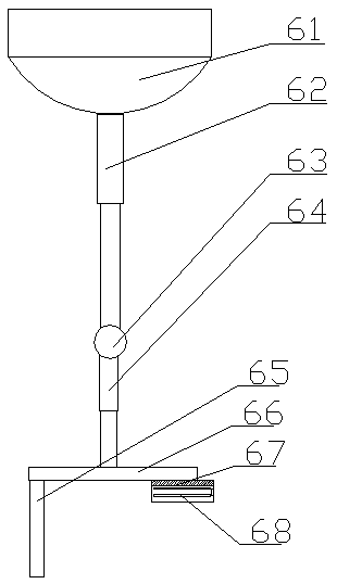
[0037] The deicing mechanism 6 includes a third two-axis platform 61 arranged on the deicing base 3, and a third auxiliary support telescopic rod 62 arranged on the third two-axis platform 61 is arranged on the The fourth two-axis platform 63 at the end of the third auxiliary support telescopic rod 62 is arranged on the fourth auxiliary support telescopic rod 64 on the fourth two-axis platform 63, a...

Embodiment 2

[0047] The difference from Embodiment 1 is that: the deicing base 3 is provided with an anti-collision metal mesh matched with the suspension airbag.

[0048] The anti-collision metal mesh used in this embodiment is preferably arranged on the surface of the airbag, and adopts the mode of elastic steel belt.

Embodiment 3

[0050] The difference between it and the second embodiment is that hydrogen gas is set in the first compression tank 4 .

[0051] The compressed gas used in this embodiment is hydrogen, which is less dangerous because it is in a low-temperature environment and produces better buoyancy.


PUM


Abstract

The invention provides a CT energy-obtaining-based power transmission line deicing device, comprising a deicing base, a suspension mechanism disposed on the deicing base, a moving mechanism disposed on the deicing base, an auxiliary support mechanism disposed on the deicing base, a deicing mechanism disposed on the deicing base, and a control mechanism disposed on the deicing base for performing coordinated control on the suspension mechanism, the moving mechanism, the auxiliary support mechanism and the deicing mechanism. The CT energy-obtaining-based power transmission line deicing device inthe invention not only does not increase the load quality of the transmission line to deice smoothly and not need to carry more energy for the device body but also can reduce the difficulty of suspension.

Description

technical field [0001] The invention relates to the technical field of power transmission line deicing equipment, in particular to a power transmission line deicing device based on CT energy acquisition. Background technique [0002] The icing disaster of electric shock lines is one of the main factors affecting the safety of transmission lines in winter. There are two solutions for the collapse of the tower, which leads to the paralysis of the transmission line. One is to enhance the design strength of the transmission line, and the other is to de-ice in time. The existing de-icing devices are divided into hand-held, Suspension or unmanned aerial vehicles are the most primitive way, which will increase the difficulty of the operator's operation, while the suspension type will increase the quality of the transmission line, and the use of unmanned aerial vehicles will increase energy consumption. And the existing deicing mechanism needs electric energy to drive, and the deic...

Claims


Application Information

Patent Timeline
IPC IPC(8): H02G7/16H02J5/00
CPCH02G7/16H02J5/005
Inventor 马旭东李小康
Owner 国网河南省电力公司邓州市供电公司
Why Eureka
Try Eureka