Hydraulic system capable of guaranteeing simultaneous working of fire-fighting cannon and large-flow fire-fighting water guns

A technology of simultaneous work and fire monitor, applied in the field of hydraulic system, can solve the problems of inability to meet the requirements of output pressure, high cost of fire trucks, low feasibility, etc., to achieve fast response, improve fire fighting and rescue capabilities, and reduce the number of effects.

Pending Publication Date: 2018-09-21
NANJING DEWOKE AUTOMATION
View PDF8 Cites 2 Cited by
  • Summary
  • Abstract
  • Description
  • Claims
  • Application Information

AI Technical Summary

Problems solved by technology

The hydraulic system equipped with fire trucks in the prior art can be adjusted to operate at the corresponding pressure when the fire monitor or the large-flow fire water nozzle is used alone, but it cannot meet the requirements of the two output pressures required when the fire monitor and the large-flow fire water nozzle are used at the same time; The function of using fire monitors and large-flow fire water guns at the same time can significantly improve the fire-fighting efficiency of a single fire truck at the fire-fighting operation site, especially suitable for narrow terrain conditions
And the fire-fighting hydraulic system of prior art can not satisfy this demand; If two fire-fighting pumps are equipped on the fire-fighting vehicle to supply water to the fire-fighting gun and the large-flow fire-fighting water gun respectively, then the cost of the fire-fighting vehicle is high, takes up more car body space, and is difficult to Arrangement, the feasibility is not high

Method used


Image

  • Hydraulic system capable of guaranteeing simultaneous working of fire-fighting cannon and large-flow fire-fighting water guns

Examples


Embodiment Construction

[0018] Below in conjunction with accompanying drawing and specific embodiment, further illustrate the present invention, should be understood that these embodiments are only for illustrating the present invention and are not intended to limit the scope of the present invention, after having read the present invention, those skilled in the art will understand various aspects of the present invention Modifications in equivalent forms all fall within the scope defined by the appended claims of this application.

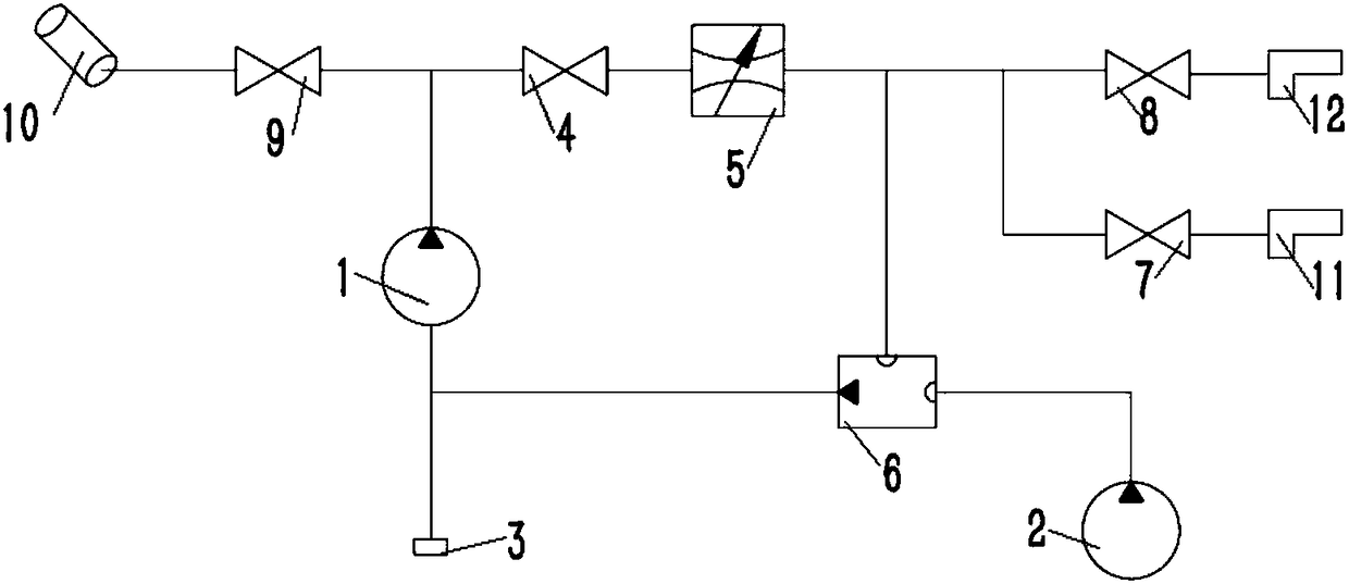
[0019] Such as figure 1 As shown, a hydraulic system that can work simultaneously for fire monitors and large-flow fire water guns, it includes: water inlet 3, fire pump 1 connected to water inlet 3 through pipelines, and the first branch connected to fire pump 1 And the second branch, the first branch is connected with the fire monitor 10, the second branch is connected with the metering valve 5, and the metering valve 5 is connected with the third branch and the fourth...


PUM


Abstract

The invention discloses a hydraulic system capable of guaranteeing simultaneous working of a fire-fighting cannon and large-flow fire-fighting water guns. The hydraulic system comprises a water inlet(3), a fire-fighting pump (1) connected with the water inlet (3) through a pipe, and a first branch and a second branch which are connected with the fire-fighting pump (1), wherein the first branch isconnected with the fire-fighting cannon (10); the second branch is connected with a metering valve (5); the metering valve (5) is connected with a third branch and a fourth branch; the third branch is connected with a self-balancing pressure relief valve (6); the fourth branch is divided into a fifth branch and a sixth branch; the fifth branch is connected with a first fire-fighting water gun (11); the sixth branch is connected with a second fire-fighting water gun (12); the self-balancing pressure relief valve (6) is connected with a gas pressurizing pump (2). The hydraulic system provided by the invention is reasonable in structural design, high in integration performance and convenient to use, can achieve two output pressures by one fire-fighting pump, can guarantee the simultaneous working of the fire-fighting cannon and the large-flow fire-fighting water guns, and is strong in practicality.

Description

technical field [0001] The invention relates to a fire-fighting equipment, in particular to a hydraulic system which is easy to use and can realize two kinds of output pressures provided by a fire-fighting pump and can work simultaneously for a fire-fighting cannon and a large-flow fire-fighting water cannon. Background technique [0002] The fire-fighting hydraulic system is used in various fire-fighting nozzles and fire-fighting cannons; its function is to provide a stable pressure water source for the fire-fighting monitors and fire-fighting nozzles to ensure the normal execution of fire-fighting operations. Since the fire monitor is fixed on the fire truck through the support, it can withstand greater recoil and work under higher water pressure; the water mist gun with small flow has less recoil and can also work under higher water pressure; and the handheld use Large-flow fire nozzles can only work at a lower pressure to reduce recoil so that firefighters can work hand-...

Claims


Application Information

Patent Timeline
Patent Type & Authority Applications(China)
IPC IPC(8): A62C31/00A62C31/28A62C37/00
CPCA62C31/00A62C31/28A62C37/00
Inventor 蒋旭东朱义马小叶
Owner NANJING DEWOKE AUTOMATION
Why Eureka
Try Eureka