A flue gas purification system involving multiple processes and a control method thereof

A flue gas purification system and multi-process technology, applied in chemical instruments and methods, separation methods, gas treatment, etc., can solve problems such as stable fluctuations in the amount of activated carbon

Active Publication Date: 2019-07-12
ZHONGYE-CHANGTIAN INT ENG CO LTD
View PDF3 Cites 0 Cited by
  • Summary
  • Abstract
  • Description
  • Claims
  • Application Information

AI Technical Summary

Problems solved by technology

[0006] Secondly, the centralized analysis subsystem needs to centrally activate the polluted activated carbon discharged from multiple adsorption subsystems. Due to the different scales of the multiple adsorption subsystems, the discharge flow rate of the polluted activated carbon is also different. In addition, the centralized analysis sub-system The polluted activated carbon processed by the system comes from the adsorption subsystems installed in different processes. Factors such as equipment failures and production plan adjustments will cause fluctuations in the stability of the quantity of activated carbon output by the adsorption subsystems in different processes. Therefore, how to control the concentration of analytical components? The balance between the system's treatment capacity for polluted activated carbon and the discharge of activated carbon from multiple adsorption subsystems is also a technical problem that is difficult for those skilled in the art to overcome

Method used


Image

  • A flue gas purification system involving multiple processes and a control method thereof
  • A flue gas purification system involving multiple processes and a control method thereof
  • A flue gas purification system involving multiple processes and a control method thereof

Examples


Embodiment Construction

[0096] Exemplary embodiments will be described in detail herein, examples of which are illustrated in the accompanying drawings. Where the following description refers to the drawings, the same numerals in different drawings refer to the same or similar elements unless otherwise indicated. The implementations described in the illustrative examples below are not intended to represent all implementations consistent with the present invention. Rather, they are merely examples of apparatus and methods consistent with some aspects of the invention as recited in the appended claims.

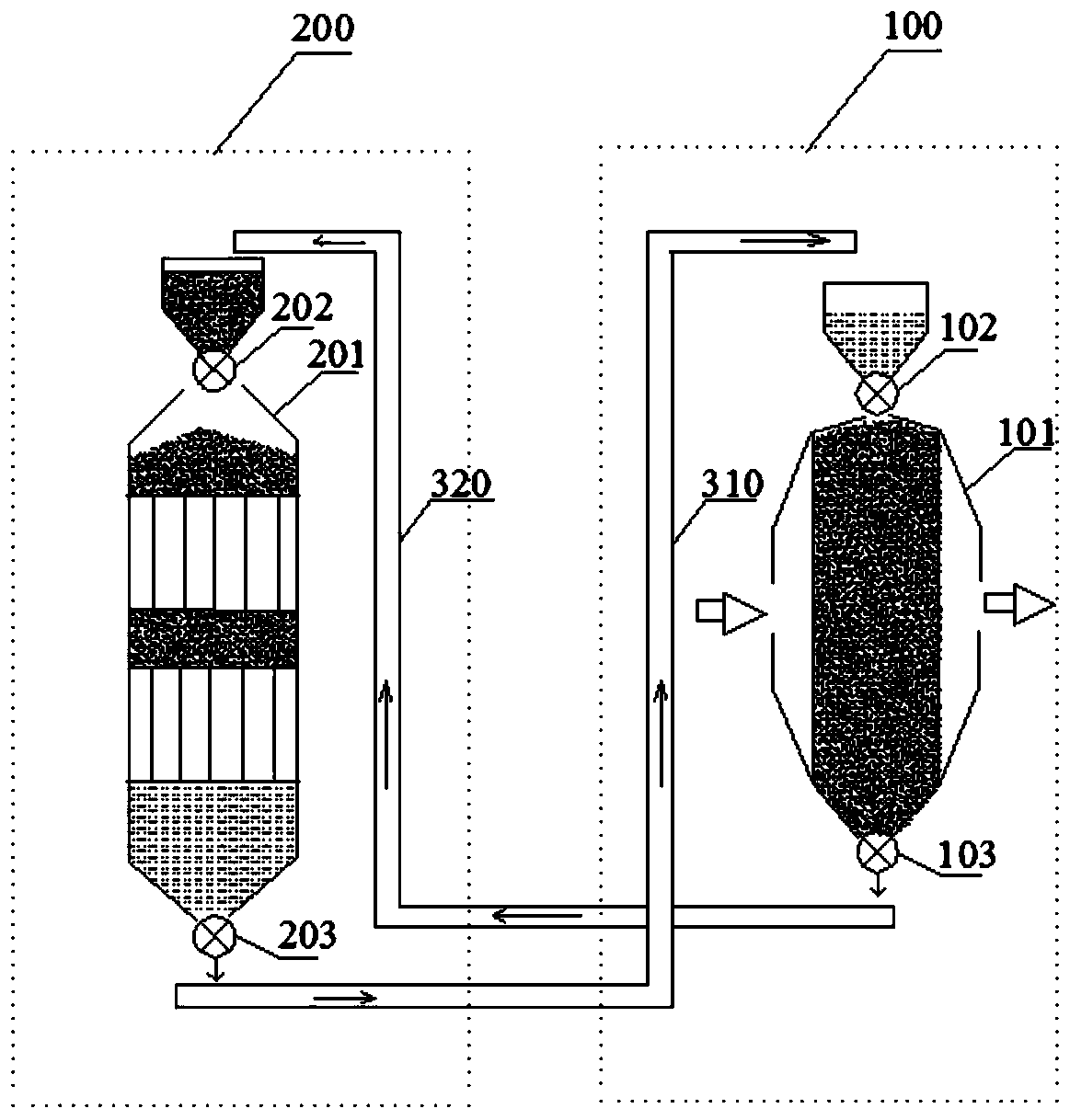
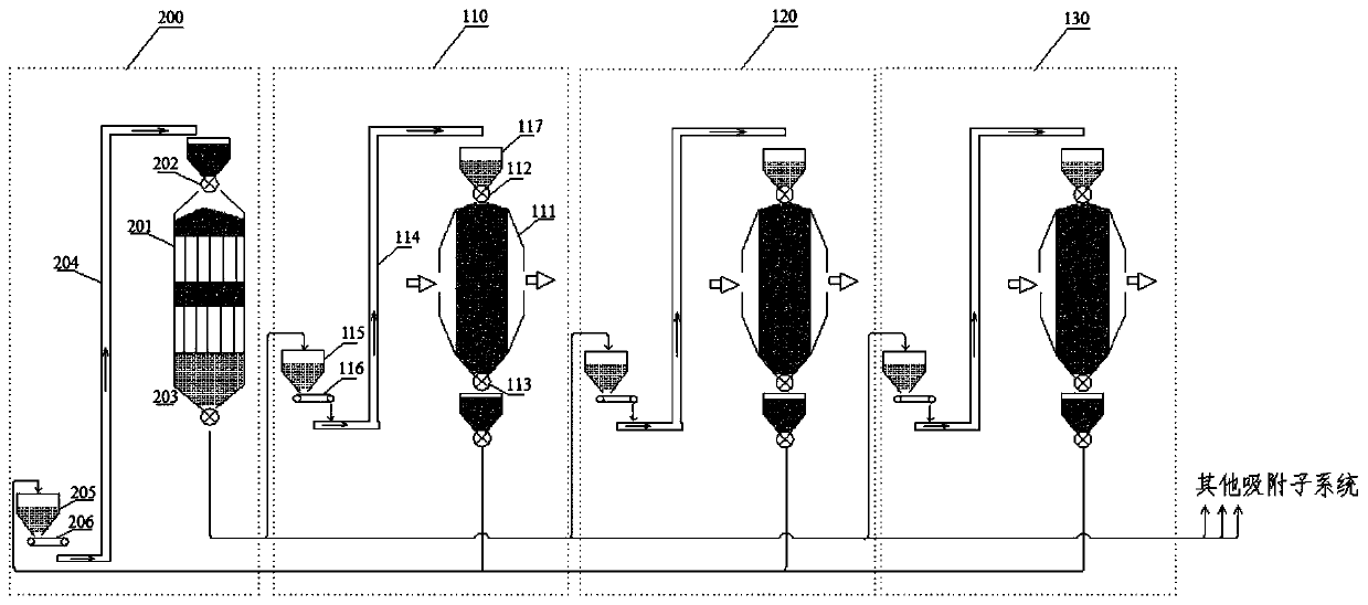
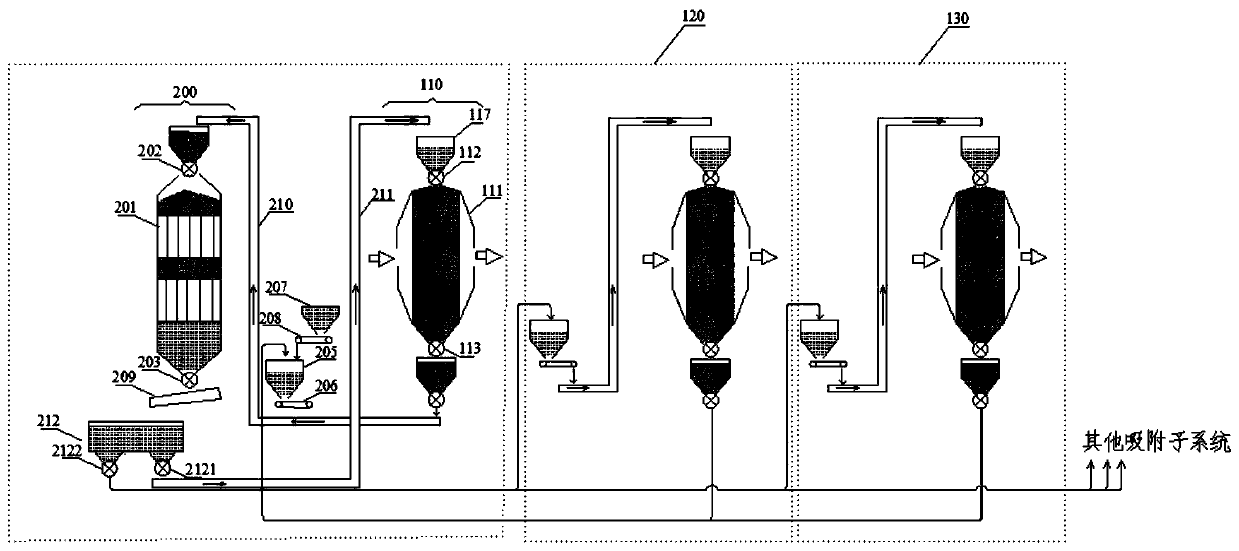
[0097] figure 2 A flue gas purification system involving multiple steps is shown, see figure 2 , the flue gas purification system includes:

[0098] A plurality of adsorption subsystems (110 / 120 / 130, etc.) respectively arranged in each flue gas discharge process, a centralized analysis subsystem 200 corresponding to the plurality of adsorption subsystems, and a transportation subsystem (not shown ...


PUM


Abstract

The present application discloses a multi-process flue gas purification system and a control method thereof. The centralized analysis subsystem is arranged in the sintering process, and forms an integrated structure with the sintering process adsorption subsystem, so that the circulation is performed in the centralized analysis subsystem and the sintering process subsystem. The activated carbon between them can be cycled through the conveying unit without additional conveying equipment, which saves transportation resources and at the same time reduces the impact of the transportation process on the operation of the system. In the present application, the centralized analysis subsystem includes a material distribution device, and the activated activated carbon is distributed to the adsorption subsystem of the sintering process through the first material distribution device, and the activated carbon flow of the centralized analysis subsystem is adjusted to that of the adsorption subsystem of the sintering process and the remaining adsorption subsystems. The activated carbon flow is balanced. By setting the working parameters of the centralized analysis subsystem feeding device, discharge device and material distribution device, on the centralized analysis subsystem side, the balance relationship between the centralized analysis subsystem and the adsorption subsystem is realized. Precise control.

Description

technical field [0001] The present application relates to the technical field of gas purification, in particular to a flue gas purification system involving multiple processes and a control method thereof. Background technique [0002] There are many processes in iron and steel enterprises that can generate flue gas emissions, such as sintering process, coking process, blast furnace ironmaking process, converter or electric furnace steelmaking process, etc. The flue gas emitted by each process contains a large amount of dust, SO 2 and NO X and other pollutants. Usually, enterprises use activated carbon flue gas purification technology to remove SO in flue gas 2 and NO X , so as to realize the clean emission of corporate exhaust gas. [0003] figure 1 An activated carbon flue gas purification system is shown, and the system includes: an adsorption subsystem 100 for purifying raw flue gas and discharging polluted activated carbon, an analysis subsystem 200 for activating...

Claims


Application Information

Patent Timeline
Patent Type & Authority Patents(China)
IPC IPC(8): B01D53/04
CPCB01D53/04B01D53/0454B01D2253/102B01D2258/0283B01D2257/302B01D2257/404B01D53/08B01D53/30B01D53/0407B01D53/02B01D53/06
Inventor 叶恒棣刘雁飞魏进超刘昌齐傅旭明杨本涛
Owner ZHONGYE-CHANGTIAN INT ENG CO LTD
Why Eureka
Try Eureka