Buried cable laying method and cable protection sleeve special for method

A cable protection sleeve and cable laying technology, which is applied to cable laying equipment, cable installation, cable installation in underground pipes, etc. ability, extended service life, and the effect of easy operation

Active Publication Date: 2018-09-21
中铁十五局集团电气化工程有限公司
View PDF6 Cites 6 Cited by
  • Summary
  • Abstract
  • Description
  • Claims
  • Application Information

AI Technical Summary

Problems solved by technology

[0004] In the rainy season, the surface water will infiltrate, so that the water in the soil will easily flow to the bottom of the cable ditch, and the space in the cable ditch is relatively small. If the water in the cable ditch is not discharged in time, the cable will be soaked. In stagnant water, due to prolonged immersion, the sheath of the cable will swell and deform, thus affecting the service life of the cable

Method used


Image

  • Buried cable laying method and cable protection sleeve special for method
  • Buried cable laying method and cable protection sleeve special for method
  • Buried cable laying method and cable protection sleeve special for method

Examples


Embodiment 1

[0072] Embodiment 1: A direct-buried cable laying method includes the following steps: re-testing S1 for cable line engineering, cable distribution plate S2, cable laying S3, cable trench backfilling S4, and stake burying S5.

[0073] The specific process of the re-test S1 of the cable line engineering line is as follows:

[0074] 1-1. Re-measure the cable laying path: According to the design and construction path map, determine the path direction of the cable, the protection of bridges, culverts, aisles, rail crossings, the relative position and number of joints, and the soil conditions of the lines, so that the optical cable lines are safe and reliable. And easy to construct and maintain. One stake every 100 meters during measurement, and additional stakes are added at special locations for joints, remainders, inflection points, rail crossings, and road crossings;

[0075] 1-2. Reasonably calculate and allocate the remaining cable: the natural bending of the cable is 2%, de...

Embodiment 2

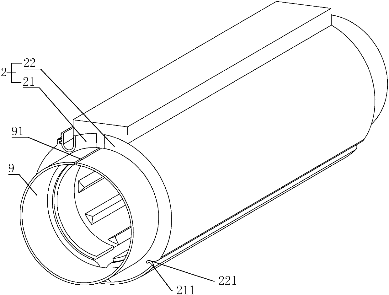
[0093] Embodiment 2: A special cable protection sleeve for direct buried cable laying method, such as figure 2 As shown, the length of each cable protection sleeve 2 is 1 meter, a flexible rubber hose 9 is arranged between adjacent cable protection sleeves 2, and the upper end of the rubber hose is provided with an opening 91, and the opening 91 can follow the cable The protective sleeve 2 is opened and opened. The arrangement of the rubber hose 9 is used to connect the adjacent cable protection sleeves 2, and at the same time, the cable protection sleeves 2 can be folded and stored so as to reduce the storage length of the cable protection sleeves 2 and reduce the length of the cable protection sleeves 2. The required storage and transportation space is described below with a single cable protection sleeve.

[0094] like figure 2 As shown in the figure, the traditional cable protection sleeve 2 is an integrally formed hollow tube structure, which not only wastes space dur...


PUM


Abstract

The invention discloses a buried cable laying method and a cable protection sleeve special for the method and belongs to the field of cable laying. According to the buried cable laying method, by improving the water storage and drainage capacity of a cable groove, the cable protection sleeve is not easily in contact with accumulated water, and accordingly the problem is solved that the cable protection sleeve swells and deforms when being soaked in the accumulated water. The buried cable laying method is characterized by comprising the following steps of S1, engineering line repetition measurement of a cable line; S2, disk distribution for a cable; S3, cable laying; S4, backfill of the cable groove; S5, burying of stakes. The third step comprises the following specific processes of 3-1, digging of the cable groove, wherein foundation pits are dug, stacks are formed, rough shaping and fine shaping are conducted, and the cable groove is poured and formed; 3-2, cable laying, wherein manual cable laying is conducted, the cable is laid at one side of the cable groove, and the cable protection sleeve wraps the cable; a specially-assigned person straightens out the cable and puts the cable into the cable groove. The buried cable laying method is suitable for buried cable laying.

Description

technical field [0001] The invention relates to the field of cable laying, in particular to a direct buried cable laying method and a special cable protection sleeve for the method. Background technique [0002] The cable laying methods are as follows: direct burying cables, laying in cable trays, laying along steel cables, laying through pipes, laying along walls with line clips and laying along cable supports in cable trenches. [0003] The direct buried cable is in accordance with the requirements of the specification. After the direct buried cable trench is dug, a sand cushion is laid on the bottom of the trench, and the sundries in the trench are removed, and then the cable is laid. A cable laying method in which a layer of bricks or concrete slabs are covered on the cable to protect the cable, and then backfilled. The direct burial laying method is generally suitable for the laying of medium and low voltage cables, which has the advantages of reducing external force d...

Claims


Application Information

Patent Timeline
Patent Type & Authority Applications(China)
IPC IPC(8): H02G1/08H02G9/06H02G3/04
CPCH02G1/08H02G3/0418H02G3/0481H02G9/06
Inventor 姚青龙王彦明朱同祁意博毛志康
Owner 中铁十五局集团电气化工程有限公司
Why Eureka
Try Eureka