
Electric power special 2M optical interface multiplexing protection channel and application method

A technology for protection channels and application methods, which is applied in the field of multiplexing protection channels for electric power dedicated 2M optical interfaces and relay protection information for electric power, and can solve problems such as poor maintainability, complex engineering implementation, and large investment, so as to improve channel reliability , The operation and maintenance interface is clear and the effect of increasing flexibility

Inactive Publication Date: 2018-09-25
国网湖北省电力有限公司荆门供电公司 +1
View PDF4 Cites 4 Cited by
  • Summary
  • Abstract
  • Description
  • Claims
  • Application Information

AI Technical Summary

Problems solved by technology

However, 2M optical / electrical conversion equipment is required for information conversion between the protection device and SDH optical transmission equipment under this channel, resulting in the lack of a unified interface standard for this application method, and the protection devices and conversion devices of different manufacturers cannot be used for each other. Technical barriers, engineering implementation is complicated, maintainability is poor, and investment is large. Due to engineering complexity, the stability and reliability of information protection channels are low

Method used


Image

  • Electric power special 2M optical interface multiplexing protection channel and application method
  • Electric power special 2M optical interface multiplexing protection channel and application method
  • Electric power special 2M optical interface multiplexing protection channel and application method

Examples


Embodiment Construction

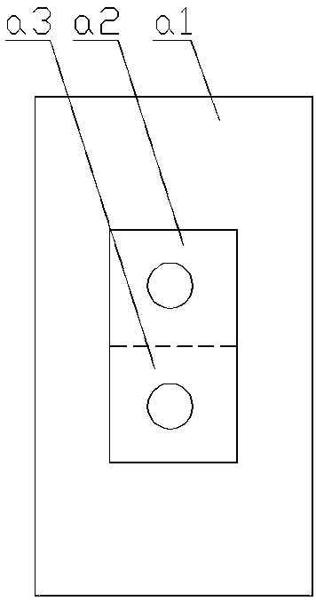
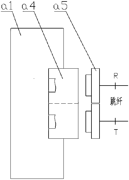
[0027] by figure 1 , figure 2 with image 3 As shown, the dedicated 2M optical interface multiplexing protection channel includes SDH optical transmission equipment, a 2M optical interface board a1 and a professional relay protection device. One side of the 2M optical interface board a1 is provided with a light receiving module a2 and The other side of the light-emitting module a3 is provided with an LC-type optical fiber socket a4. The 2M optical interface board a1 is fixedly installed on the SDH optical transmission equipment. The relay protection professional protection device is connected to the 2M optical interface board a1 through a tail cable. The receiving module a2 and the light emitting module a3 are directly connected. The SDH optical transmission device is plugged into the LC fiber socket a4 on the other side of the 2M optical interface board through the LC fiber plug a5. The SDH optical transmission device adopts It is a ZXMP-S385 type transmission equipment, and t...


PUM


Abstract

The invention discloses a special 2M optical interface multiplexing protection channel and an application method. One side of a 2M optical interface board is provided with a light receiving module anda light emitting module, and the other side is provided with an LC type optical fiber jack; the 2M optical interface board is fixedly arranged on SDH optical transmission equipment; a relay protection professional protection device is directly connected with the light receiving module and the light emitting module on one side of the 2M optical interface board through a tail cable; and the SDH optical transmission equipment is plugged into the LC type optical fiber jack in the other side of the 2M optical interface board through a LC type optical fiber plug. The special 2M optical interface multiplexing protection channel has the advantages of realizing unified encapsulation of 2M optical signals, realizing direct connection, enhancing the channel reliability, saving investment, and makinga professional operation and maintenance interface clearer. A 2M optical interface protection channel mode is adopted, so that the flexibility in ensuring a service channel between power substationsis enhanced. The special 2M optical interface multiplexing protection channel is suitable for power optimization, new construction, emergency support and other application scenarios.

Description

Technical field [0001] The present invention relates to the technical field of relay protection information for electric power, and more specifically to the technical field of multiplexed protection channels for power dedicated 2M optical interfaces. Background technique [0002] There are two types of optical fiber communication channels that transmit relay protection information: dedicated channels and multiplexed channels. The 2Mbps multiplexed protection channel occupies less fiber core resources, has unlimited transmission distance, flexible operation mode adjustment, and supports remote monitoring. It is generally widely used as a circuit protection channel. However, 2M optical / electrical conversion equipment is required for information conversion between the protection device under this channel and the SDH optical transmission equipment. This results in the lack of a unified interface standard for this application method. The protection devices and conversion devices betwe...

Claims


Application Information

Patent Timeline
IPC IPC(8): H04B10/079H04B10/25H04B10/40
CPCH04B10/07953H04B10/25891H04B10/40
Inventor 胡邦权范勇锋
Owner 国网湖北省电力有限公司荆门供电公司
Learn More