Actuating mechanism system of automatic driving robot

An actuator and automatic driving technology, applied in the testing of machines/structural components, instruments, vehicles, etc., can solve the problems of incomplete statistics, loss of control of the test vehicle, slow response speed, etc., to improve the ride comfort, adjust Simple and convenient, the effect of reducing the size of the mechanism

Pending Publication Date: 2022-07-01
SHENYANG SIASUN ROBOT & AUTOMATION
View PDF0 Cites 0 Cited by
  • Summary
  • Abstract
  • Description
  • Claims
  • Application Information

AI Technical Summary

Problems solved by technology

[0005] However, there are some defects in the actuators in the existing technology. For example, the German STAHLE company has developed a pedal brake robot. The motor drives the wire rope wheel to rotate, the rope wheel rotates and winds the wire rope, the wire rope pulls the guide shaft, and the guide shaft pushes the brake pedal of the test vehicle. Since the flexible wire rope is used, and the mechanism is reset by the compression spring, this causes the mechanism to push the pedal in the positive direction. , the servo motor has to overcome the ever-increasing spring force, and this part of the spring force is a redundant force for the mechanism. The power utilization rate of the whole mechanism is low and the response speed is slow. In addition, when the mechanism pushes the pedal forward, the sudden change The tension is all concentrated on the steel wire rope, and there is a risk of breaking the steel wire rope. There is incomplete statistics. When the structure is actually used, it breaks once every 1000 hours on average.
After the breakage, the brake actuator is out of control, which leads to the loss of control of the vehicle brake, and the safety hazard is extremely high
Another example is the German STAHLE company developed an accelerator brake robot, the product is installed on the test vehicle, its pendulum is in line contact with the accelerator pedal, when the accelerator pedal is stepped forward, the rotation angle of the accelerator pedal is equal to the rotation of the servo motor. There is a specific functional relationship, but when the accelerator pedal is reversely reset, the relative sliding displacement between the swing rod and the accelerator pedal will occur, and the relative rotation relationship is extremely complicated, and it is extremely difficult to achieve precise reset control. When testing on bumpy roads, the position of the swing lever and the accelerator pedal is likely to be out of contact, causing the test vehicle to lose control

Method used


Image

  • Actuating mechanism system of automatic driving robot
  • Actuating mechanism system of automatic driving robot
  • Actuating mechanism system of automatic driving robot

Examples


Embodiment Construction

[0038] The present invention will be described in further detail below in conjunction with the accompanying drawings.

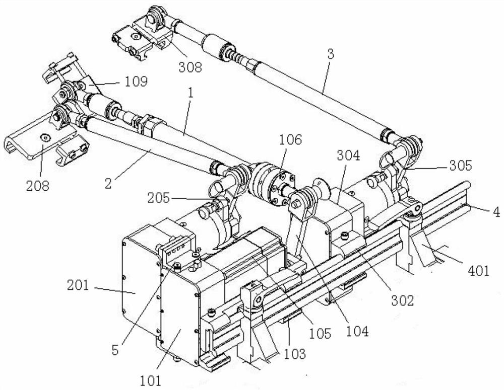
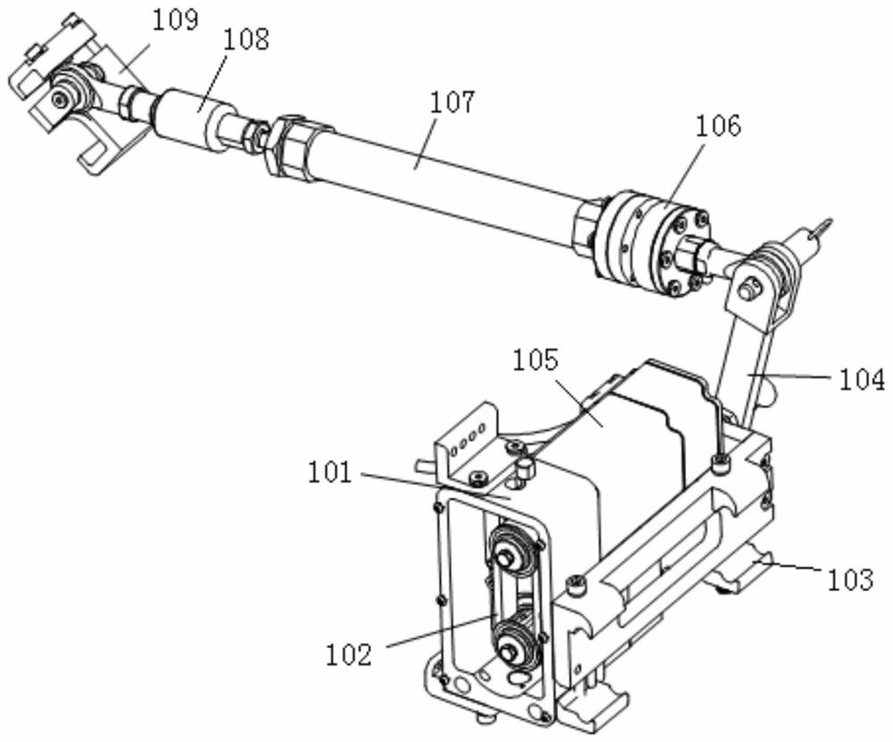
[0039] like Figures 1 to 12 As shown, the present invention includes a brake actuator 1, a clutch actuator 2, a throttle actuator 3 and a seat rail 4, wherein the brake actuator 1 includes a brake drive device, a brake sway rod 104, a brake link assembly and brake pedal adapter 109, and the brake swing rod 104 is driven to swing by the brake drive device, the upper end of the brake swing rod 104 is hinged with the rear end of the brake link assembly, and the front end of the brake link assembly is connected with the brake pedal adapter 109 Hinged, the clutch actuator 2 includes a clutch drive device, a clutch swing rod 205, a clutch link assembly and a clutch pedal adapter 208, and the clutch swing rod 205 is driven to swing by the clutch drive device. The upper end of the clutch swing rod 205 is connected to the rear end of the clutch link assembly. Hinged...


PUM


Abstract

The invention relates to an actuating mechanism system of an automatic driving robot, which is characterized in that a brake swing rod in a brake actuating mechanism is driven by a brake driving device to swing, the rear end of a brake connecting rod assembly is hinged with the brake swing rod, the front end of the brake connecting rod assembly is hinged with a brake pedal adapter, and a clutch swing rod in a clutch actuating mechanism is driven by a clutch driving device to swing; the rear end of a clutch connecting rod assembly is hinged to a clutch swing rod, the front end of the clutch connecting rod assembly is hinged to a clutch pedal adapter, an accelerator swing rod in the accelerator executing mechanism is driven by an accelerator driving device to swing, the rear end of the accelerator connecting rod assembly is hinged to the accelerator swing rod, and the front end of the accelerator connecting rod assembly is hinged to an accelerator pedal adapter. The brake driving device and the accelerator driving device are both provided with sliding seats which are hung on the seat sliding rail, and the clutch driving device is fixedly connected with the brake driving device. The device is simple in action relation, high in control precision, rapid in response and small in occupied space, has an emergency protection function, and can drive the accelerator pedal and the clutch pedal to automatically reset when switched to a manual driving mode.

Description

technical field [0001] The invention relates to the field of automatic driving robots used for vehicle detection, in particular to an automatic driving robot actuator system. Background technique [0002] With the development of new technologies in the automobile industry, people have put forward higher and higher requirements for the safety and reliability of automobiles, which requires automobile manufacturers to do a lot of stability, safety and reliable durability tests on automobiles. Improve the level of automotive technology. [0003] With the continuous improvement of automotive testing requirements, some environments cannot be completed by humans, or are dangerous to human drivers. At this time, automotive testing can be completed by autonomous driving robots. Compared with human test drivers, autonomous driving robots have the advantages of high-precision controllability, good repeatability, and strong fatigue durability, especially road test driving robots, which...

Claims


Application Information

Patent Timeline
Patent Type & Authority Applications(China)
IPC IPC(8): G01M17/007
CPCG01M17/007
Inventor 郭涛邱继红张威毛文霆高明磊
Owner SHENYANG SIASUN ROBOT & AUTOMATION
Why Eureka
Try Eureka