Clamp special for cavity-like part bevel drilling

A technology for special fixtures and parts, which is applied in the field of special fixtures for slant drilling of cavity parts, can solve the problems of poor position accuracy of holes to be machined, poor machining quality of workpieces, and easy deformation of workpieces, so as to achieve short processing cycles and high production efficiency. , to meet the effect of mass production

Active Publication Date: 2018-09-28
HARBIN JIANCHENG GRP
View PDF7 Cites 3 Cited by
  • Summary
  • Abstract
  • Description
  • Claims
  • Application Information

AI Technical Summary

Problems solved by technology

[0004] The present invention aims to solve the problem that the existing workpiece is easily deformed due to inconvenient clamping, and the position accuracy of the hole to be processed is poor, which leads to the poor processing quality of the workpiece, and further provides a special tool for inclined-plane drilling of cavity-type parts. fixture

Method used


Image

  • Clamp special for cavity-like part bevel drilling
  • Clamp special for cavity-like part bevel drilling
  • Clamp special for cavity-like part bevel drilling

Examples


specific Embodiment approach 1

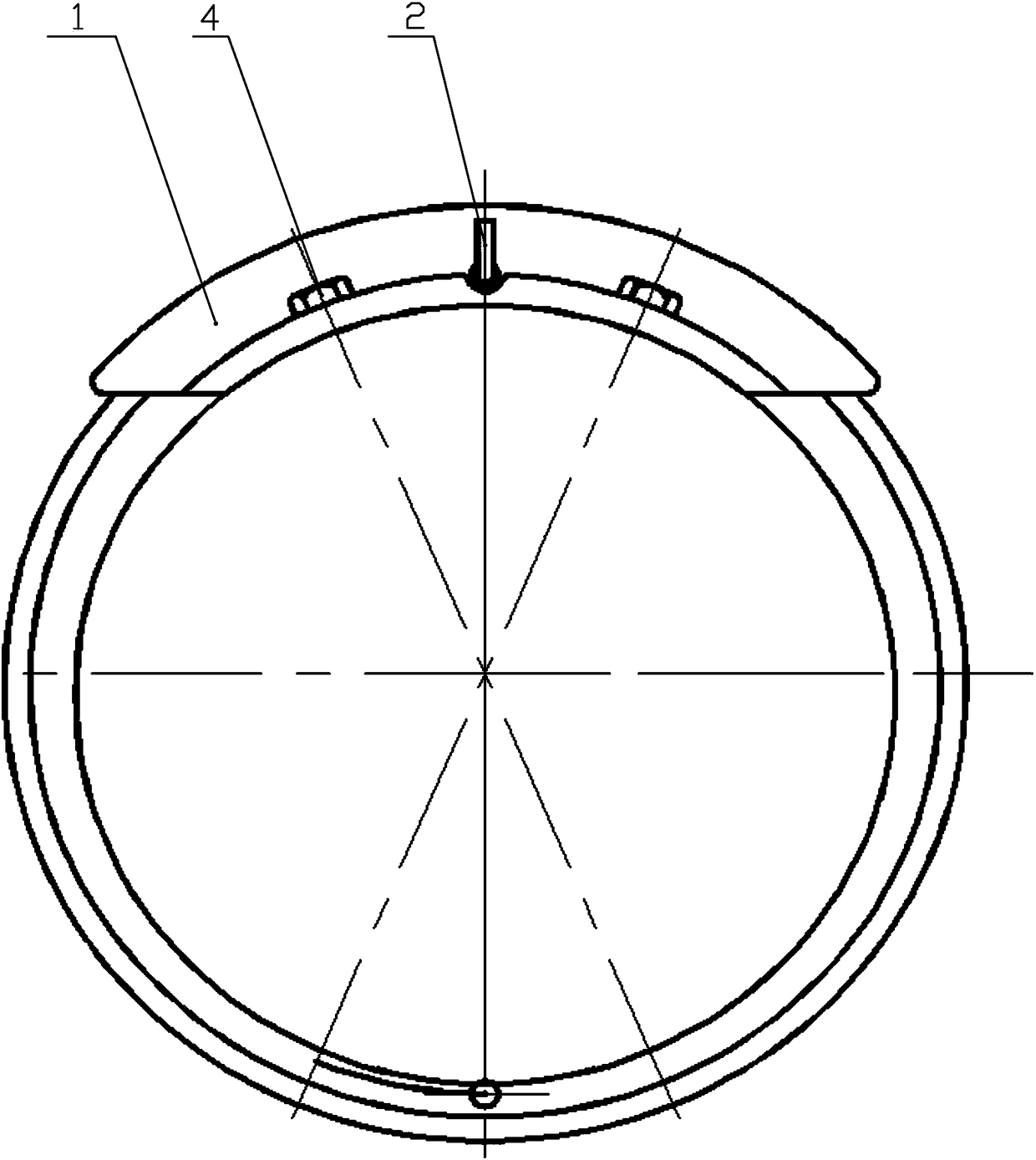
[0028] Specific implementation mode one: combine Figure 1-13 Describe this embodiment, a special fixture for drilling inclined planes of cavity parts, which includes a template body 1, a positioning pin 2, two drill sleeves 3 and two fixing screws 4, and the template body 1 includes from left to The first arc-shaped positioning section 11, the arc-shaped plate 12 and the second arc-shaped positioning section 13, which are coaxially fixed in sequence on the right, the central axis of the drill body 1 coincides with the central axis of the workpiece, wherein the first arc-shaped positioning The inner arc surface of section 11 is in close contact with the outer wall of the circular platform section 101 of the workpiece, the inner arc surface of the second arc positioning section 13 is in close contact with the outer wall of the second cylindrical section 102 of the workpiece, and the left side wall of the arc-shaped plate 12 is in close contact with the workpiece circular platfor...

specific Embodiment approach 2

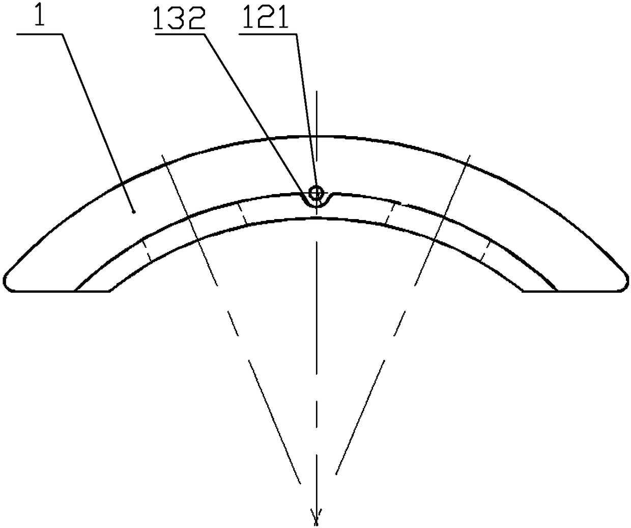
[0034] Specific implementation mode two: combination figure 2 and Figure 4 To illustrate this embodiment, the positioning hole 131 is an oval long hole. Such a design ensures accurate positioning of the arc-shaped plate 12 and the second arc-shaped positioning segment 13 on the workpiece. Other compositions and connections are the same as those in the first embodiment.

specific Embodiment approach 3

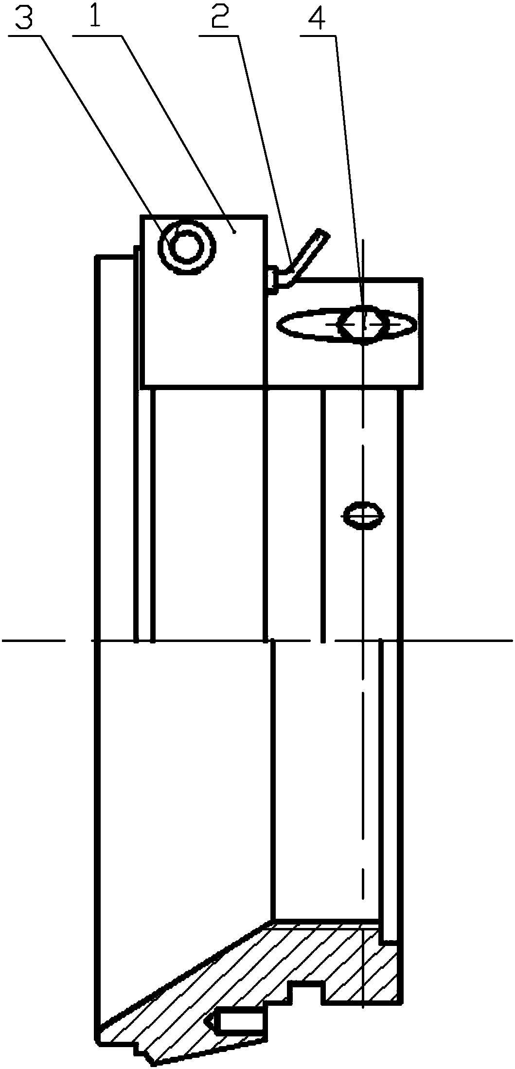
[0035] Specific implementation mode three: combination figure 1 , 2 , 7 and 8 illustrate this embodiment, the positioning pin 2 includes a third cylindrical section 21 and a handle 22 obliquely fixed on one end of the third cylindrical section 21, and an annular boss is fixed on the end of the third cylindrical section 21 close to the handle 22 23. During installation, the third cylindrical section 21 is sequentially inserted into the first through hole 121 and the pin hole 104 on the workpiece. Designed in this way, the third cylindrical section 21 plays the role of fixing the arc-shaped plate 12 and the workpiece during installation, and the gap between the third cylindrical section 21 and the pin hole 104, and between the third cylindrical section 21 and the first through hole 121 are uniform. For a tight fit. The annular boss 23 acts as a limiter for the third cylindrical section 21, and the handle 22 facilitates the installation and disassembly of the positioning pin 2...


PUM


Abstract

The invention discloses a clamp special for cavity-like part bevel drilling, and belongs to the technical field of mechanical clamps. According to the clamp special for cavity-like part bevel drilling, the problems that an existing workpiece is inconvenient to mount and clamp, and consequently the workpiece is likely to deform, the position precision of to-be-machined holes is poor, and accordingly the machining quality of the workpiece is poor are solved. The central axis of a drill jig body coincides with the central axis of a workpiece, the inner arc surface of a first arc-shaped positioning section closely makes contact with the outer wall of the circular table section of the workpiece, the inner arc surface of a second arc-shaped positioning section closely makes contact with the outer wall of the second cylindrical section of the workpiece, and the left side wall of an arc-shaped plate closely makes contact with the small end of the circular table section of the workpiece; and the arc-shaped plate is fixedly connected with the workpiece through a positioning pin closely mounted in a penetrating mode in a first through hole, the second arc-shaped positioning section is fixedlyconnected with the workpiece through two fixing screws correspondingly mounted in a penetrating mode in two positioning holes, a through groove is formed in the outer arc surface of the second arc-shaped positioning section in the axis direction of the second arc-shaped positioning section, and two second through holes are coaxial with the two to-be-machined holes of the workpiece correspondingly. The clamp special for cavity-like part bevel drilling is used for large cavity-like part bevel drilling.

Description

technical field [0001] The invention relates to a special clamp for inclined-plane drilling of cavity parts, which belongs to the technical field of mechanical clamps. Background technique [0002] a workpiece (such as Figure 10-13 ) is a large-scale cavity structure, which includes a first cylindrical section 100, a circular platform section 101 and a second cylindrical section 102 that are sequentially fixed coaxially as one, wherein the small end of the circular platform section 101 is fixedly connected to the second cylindrical section 102, The second cylindrical section 102 is processed with an annular groove 103 along its circumferential direction, and the small end of the circular truncated section 101 is provided with two pin holes 104 symmetrically about its center line, and the center line of each pin hole 104 is aligned with the center of the circular truncated section 101. The outer wall of the second cylindrical section 102 is evenly distributed with several th...

Claims


Application Information

Patent Timeline
Patent Type & Authority Applications(China)
IPC IPC(8): B23B47/28B23Q3/06
Inventor 李利华张永利
Owner HARBIN JIANCHENG GRP
Why Eureka
Try Eureka