
Drill bit guide sleeve device of precise drilling machine

A technology of machine head and drilling machine, which is applied in the direction of drilling/drilling equipment, parts of boring machine/drilling machine, positioning measurement in boring machine/drilling machine, etc. The effect of changing the time of guide sleeve, improving stability and reducing cost

Pending Publication Date: 2018-09-28
丰元智能科技(东莞)有限公司
View PDF0 Cites 0 Cited by
  • Summary
  • Abstract
  • Description
  • Claims
  • Application Information

AI Technical Summary

Problems solved by technology

[0002] The drill bit guide sleeve device of the precision drilling machine in the prior art is arranged on one side of the machine head. If the drill bit is guided by this unilateral guiding mode, it has the following disadvantages: 1. The drill bit guide sleeve device is used to guide the drill bit. When guiding, the vibration of the drill bit will be transmitted to the drill bit guide bushing device. Since the drill bit guide bushing device is unilaterally slid and fixedly installed on one side of the machine head, its anti-vibration ability is low, and the drill bit cannot be stably guided, which will lower the drill bit. 2. When the drill guide device is moving up and down, it is easy to shake, which will also affect the processing accuracy; 3. Since the drill guide sleeve device is set on one side, it will cause one side of the machine head to be heavy , when the drill bit is working, the machine head will be shifted to one side, which will cause the drill bit to be unable to guarantee that it is perpendicular to the workpiece for processing

Method used


Image

  • Drill bit guide sleeve device of precise drilling machine
  • Drill bit guide sleeve device of precise drilling machine
  • Drill bit guide sleeve device of precise drilling machine

Examples


Embodiment Construction

[0019] The technical solutions of the present invention are clearly and completely described below, and obviously, the described embodiments are part of the embodiments of the present invention, but not all of them. Based on the embodiments of the present invention, all other embodiments obtained by persons of ordinary skill in the art without making creative efforts belong to the protection scope of the present invention.

[0020] In the description of the present invention, it should be noted that the terms "center", "upper", "lower", "left", "right", "vertical", "horizontal", "inner", "outer" etc. The indicated orientation or positional relationship is based on the orientation or positional relationship shown in the drawings, and is only for the convenience of describing the present invention and simplifying the description, rather than indicating or implying that the referred device or element must have a specific orientation, or in a specific orientation. construction and...


PUM


Abstract

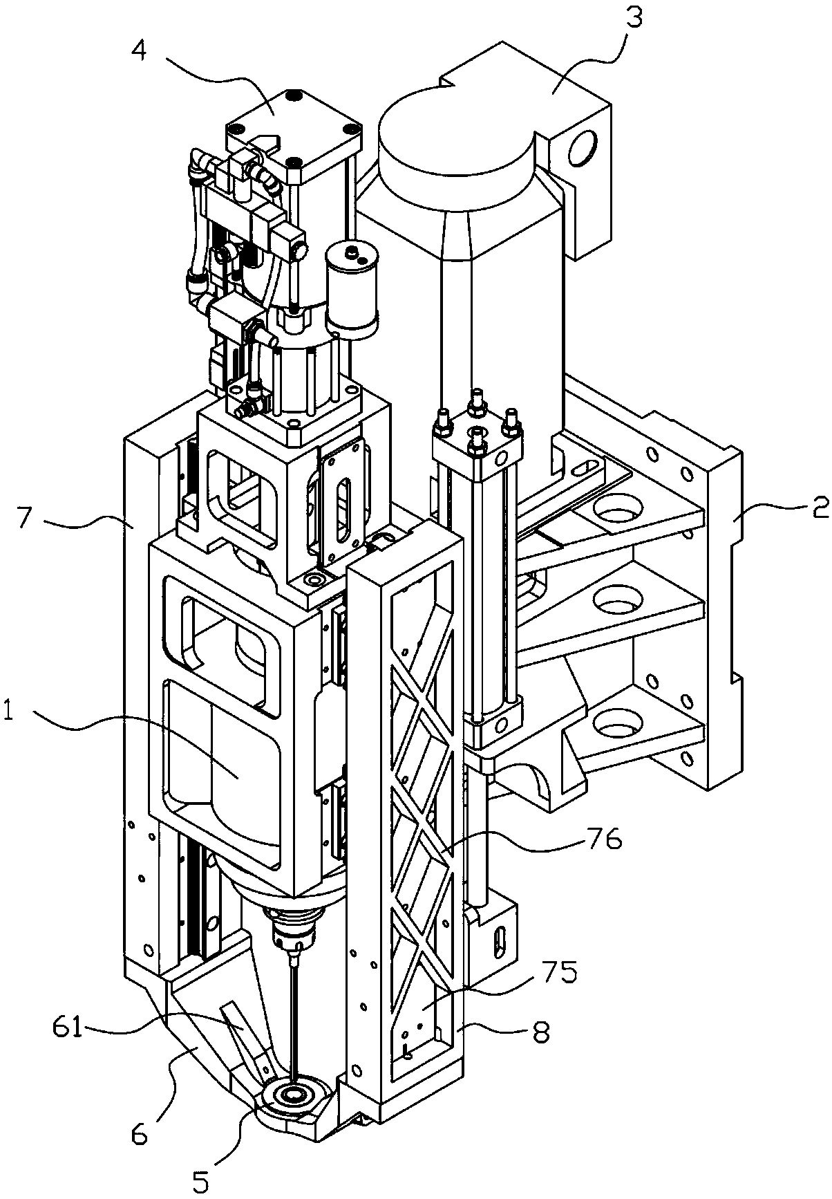
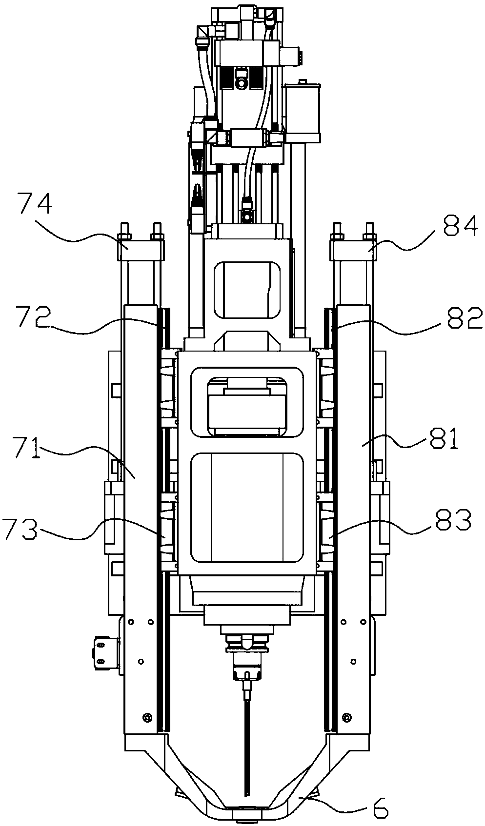
The invention provides a drill bit guide sleeve device of a precise drilling machine. The device comprises a machine head, a machine head mounting base, a motor, a cutter beating device, a guide sleeve and a guide sleeve lifting driving device; the guide sleeve lifting driving device comprises a connecting piece, a first lifting module and a second lifting module; the first lifting module is arranged on the left side of the machine head; the second lifting module is arranged on the right side of the machine head; a mounting hole for mounting the guide sleeve is formed in middle of the connecting piece; the guide sleeve is mounted in the mounting hole; the guide sleeve comprises a gland, a first guide sleeve, a transition sleeve and a second guide sleeve; the second guide sleeve is mountedat the bottom of the first guide sleeve after sleeving the transition sleeve; and after the gland sleeves the lower part of the second guide sleeve, the second guide sleeve is mounted at the bottom ofthe first guide sleeve. Through use of two-edge stressing, the device achieves better vibration resistance, greatly improves the drill bit stability, is suitable for two different chip drilling modes, greatly reduces the replacement time of the guide sleeve of the precise drilling machine, and reduces the cost.

Description

technical field [0001] The invention relates to the field of precision drilling machines, in particular to a drill bit guide sleeve device of the precision drilling machine. Background technique [0002] The drill bit guide sleeve device of the precision drilling machine in the prior art is arranged on one side of the machine head. If the drill bit is guided by this unilateral guiding mode, it has the following disadvantages: 1. The drill bit guide sleeve device is used to guide the drill bit. When guiding, the vibration of the drill bit will be transmitted to the drill bit guide bushing device. Since the drill bit guide bushing device is unilaterally slid and fixedly installed on one side of the machine head, its anti-vibration ability is low, and the drill bit cannot be stably guided, which will lower the drill bit. 2. When the drill guide device is moving up and down, it is easy to shake, which will also affect the processing accuracy; 3. Since the drill guide sleeve devi...

Claims


Application Information

Patent Timeline
IPC IPC(8): B23B49/02
CPCB23B49/02
Inventor 晁江波
Owner 丰元智能科技(东莞)有限公司
Learn More