
Cutting machine having dust removal function

A cutting machine and functional technology, applied in metal processing machinery parts, maintenance and safety accessories, metal processing equipment, etc., can solve the problems of low production efficiency, large processing workload, poor dust removal effect, etc., to achieve fast airflow and effective Good results

Inactive Publication Date: 2018-09-28
杨梅姣
View PDF0 Cites 1 Cited by
  • Summary
  • Abstract
  • Description
  • Claims
  • Application Information

AI Technical Summary

Problems solved by technology

[0002] As the industrial development of modern machinery is getting faster and faster, the requirements for cutting quality and accuracy are constantly improving. In order to meet the requirements for cutting materials, the development of steel pipe cutting machines is also getting faster and faster. In the process of mechanical processing, in the past, The cutting method is manual cutting, which is flexible and convenient, but the quality of manual cutting is poor, the size error is large, the material waste is large, and the follow-up processing workload is large. At the same time, the working conditions are harsh and the production efficiency is low. The invention of the steel pipe cutting machine makes cutting more convenient. The cutting efficiency and quality have been greatly improved, but the steel pipe cutting machines on the market often produce a lot of metal debris or dust when cutting, these dust and metal debris will float in the air, inhaling these will cause It causes great harm to the human body. Although there are steel pipe cutting machines that can remove dust, the dust removal function of these steel pipe cutting machines is not perfect, and only relatively large metal debris and dust can be removed, and the dust removal effect is poor.

Method used


Image

  • Cutting machine having dust removal function
  • Cutting machine having dust removal function
  • Cutting machine having dust removal function

Examples


Embodiment Construction

[0023] The following will clearly and completely describe the technical solutions in the embodiments of the present invention with reference to the accompanying drawings in the embodiments of the present invention. Obviously, the described embodiments are only some, not all, embodiments of the present invention. Based on the embodiments of the present invention, all other embodiments obtained by persons of ordinary skill in the art without making creative efforts belong to the protection scope of the present invention.

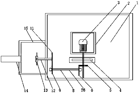
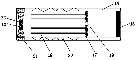
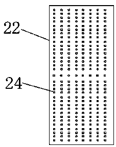
[0024] see Figure 1-6 , the present invention provides a technical solution: a cutting machine with dust removal function, including a table body 1, the table body 1 is used to place steel pipes, and cut the steel pipes, the inside of the table body 1 is fixedly installed with a motor box 2, the motor box 2 is used to fix and place the motor 3. The motor box 2 is arranged inside the table body 1, which saves space. The inside of the motor box 2 is fixedly ins...


PUM


Abstract

The invention discloses a cutting machine having the dust removal function. The cutting machine comprises a table body. A motor box is fixedly mounted inside the table body. A motor is fixedly mountedinside the motor box. An output shaft of the motor penetrates the motor box. A cutting blade is fixedly connected to the end, exposed out of the motor box, of the output shaft of the motor and is intransmission connection with a fan inside a dust suction box through a transmission device. The dust suction box is connected to one side of the table body in a clamped manner, and a filter pipe is arranged at the other side of the dust suction box. The cutting machine is provided with the fan, and air with dust can move into a dust collection box in the cutting process; by means of a filter screen, particles floating in the air can be filtered out; by means of conducting wires and conducting plates, metal chippings mixed with the air can be adsorbed; by means of a filter tip, tiny dust in theair can be filtered out, and the dust removal effect is achieved; and the problem that the dust and the metal chippings entering the air are harmful to health of human bodies is solved.

Description

technical field [0001] The invention relates to the technical field of cutting, in particular to a cutting machine with dust removal function. Background technique [0002] As the industrial development of modern machinery is getting faster and faster, the requirements for cutting quality and accuracy are constantly improving. In order to meet the requirements for cutting materials, the development of steel pipe cutting machines is also getting faster and faster. In the process of mechanical processing, in the past, The cutting method is manual cutting, which is flexible and convenient, but the quality of manual cutting is poor, the size error is large, the material waste is large, and the follow-up processing workload is large. At the same time, the working conditions are harsh and the production efficiency is low. The invention of the steel pipe cutting machine makes cutting more convenient. The cutting efficiency and quality have been greatly improved, but the steel pipe ...

Claims


Application Information

Patent Timeline
IPC IPC(8): B23Q11/00
CPCB23Q11/0042B23Q11/0046B23Q11/0064
Inventor 杨梅姣
Owner 杨梅姣
Learn More