Drawing pin driving mechanism of drawing pin strip forming machine

A technology of drawing pins and nailing rods, applied in the field of nailing machines, which can solve the problems of troublesome nailing and low efficiency of nailing

Active Publication Date: 2018-09-28
GUANGDONG MINGHUI PNEUMATIC TECH CO LTD
View PDF7 Cites 2 Cited by
  • Summary
  • Abstract
  • Description
  • Claims
  • Application Information

AI Technical Summary

Problems solved by technology

[0002] The existing nailing machines need to be installed with staples one by one, so the staples are very troublesome and the efficiency of the staples is very low

Method used


Image

  • Drawing pin driving mechanism of drawing pin strip forming machine
  • Drawing pin driving mechanism of drawing pin strip forming machine
  • Drawing pin driving mechanism of drawing pin strip forming machine

Examples


Embodiment Construction

[0045] The present invention will be further described below in conjunction with the accompanying drawings and embodiments.

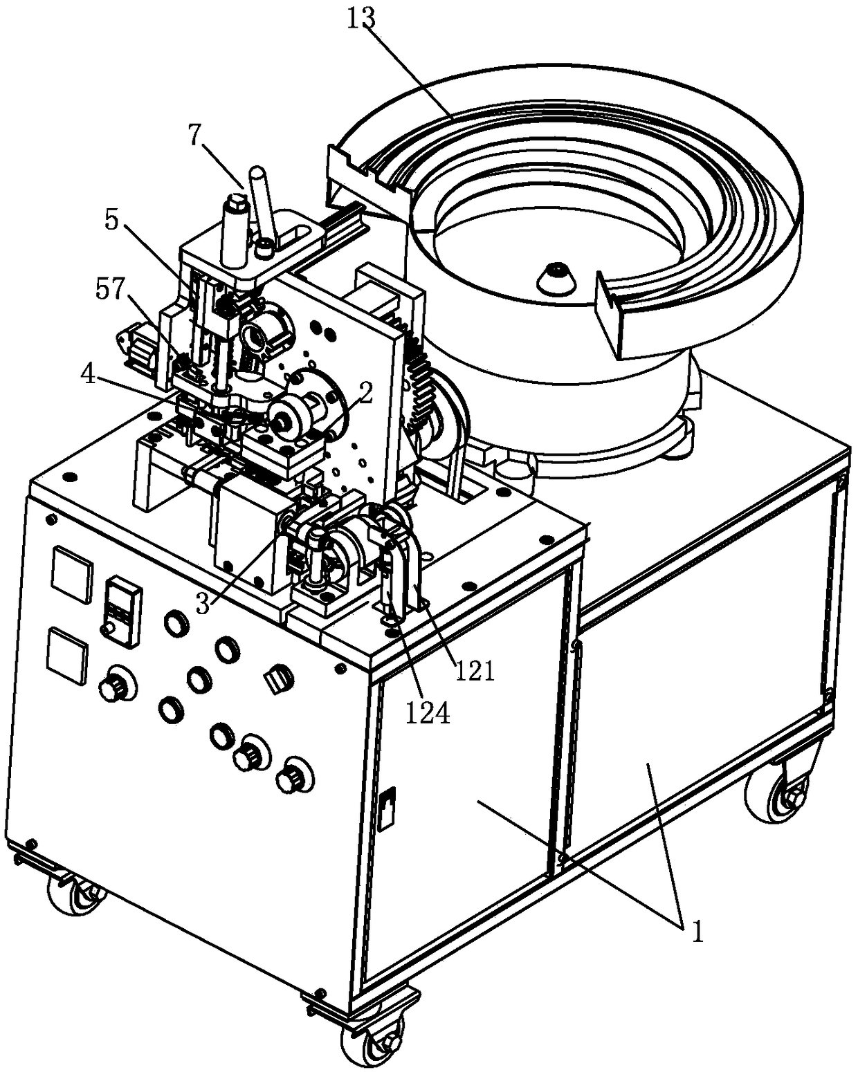
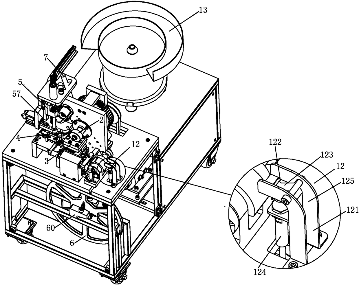
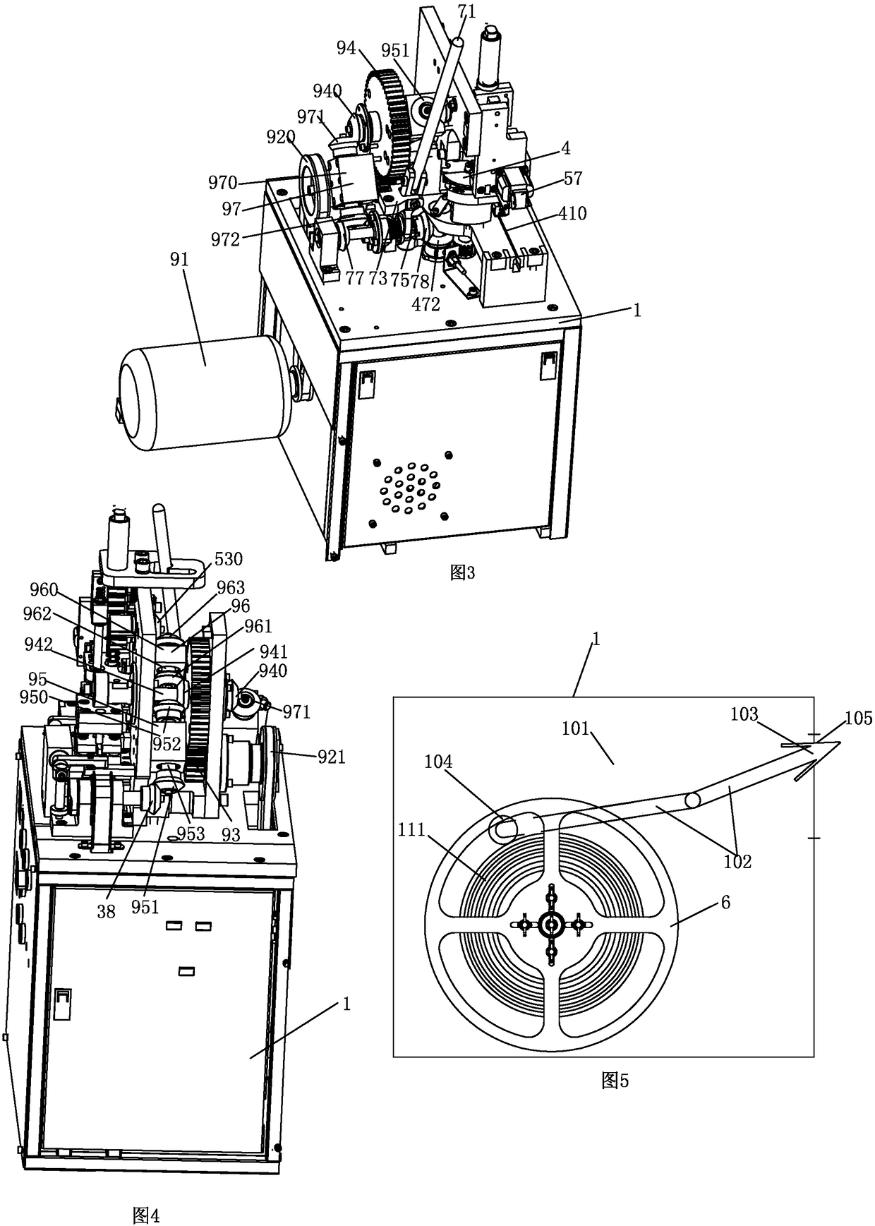
[0046]see Figure 1 to Figure 30 As shown, a thumbtack slitting machine includes a frame 1, a control device (not shown in the figure), a thumbtack vibrating feeding tray 13, a driving mechanism, a rubber strip ring fixed wheel 6, a punching and trimming mold 2, a glue pressing Strip mechanism 3, nail feeding mechanism 4, manual clutch mechanism 7, nailing mechanism 5 and rubber strip cutting mechanism 57. The control device is arranged on the frame 1 and is used to control the synchronous operation and stop of the whole drawing pin slitting machine. The thumbtack vibrating feed tray 13 is arranged on the frame 1 and is used to vibrate and convey the thumbtacks 9 to the nail feeding mechanism 4 . The driving mechanism is located on the frame 1 and is used to drive the bead pressing mechanism, the nail feeding mechanism 4, the nailing mechanism 5, the ...


PUM


Abstract

The invention relates to a drawing pin driving mechanism of a drawing pin strip forming machine. The drawing pin driving mechanism of the drawing pin strip forming machine comprises a base body, a sliding block, a driving and unlocking gear, a buffer assembly, a second bevel gear, a drawing pin driving rod, a jacking reset spring and a locking buckle plate. The drawing pin driving rod is vertically arranged on the sliding block. The sliding block is provided with a driven rack and a limiting buckle groove. The driving and unlocking gear is meshed with the driven rack. The driving and unlockinggear is provided with driving teeth. According to the drawing pin driving mechanism of the drawing pin strip forming machine, the driving and unlocking gear and the locking buckle plate are used forunlocking and carrying out driving to push the sliding block to descend at the same time so that the sliding block can drive the drawing pin driving rod to move downwards to drive drawing pins, the locking buckle plate locks the sliding block again every time the sliding block resets to rise till the next time of unlocking and driving descent of the driving and unlocking gear, and therefore, the purpose of driving the drawing pins one by one with the drawing pin driving mechanism is achieved. When a user loads drawing pins to a drawing pin driving machine, the user only needs to install a rubber strip, it is achieved that more than one drawing pin is installed at one time, and therefore, the drawing pin loading efficiency of the drawing pin driving machine is improved.

Description

technical field [0001] The invention relates to the technical field of nailing machines, in particular to a nailing mechanism of a pushpin striping machine. Background technique [0002] The existing nailing machines need to install the staples one by one, so the staples are very troublesome and the efficiency of the staples is very low. Contents of the invention [0003] The object of the present invention is to provide a nailing mechanism of a pushpin striping machine capable of driving a plurality of pushpins on the rubber strip, thereby improving the binding efficiency of the nailing machine and facilitating the binding of the user. The thumbtack stripping machine can put multiple thumbtacks on the rubber strips. When the user nails the nailing machine, he only needs to install the rubber strips to realize a one-time installation of multiple thumbtacks. The installation is very convenient, thereby improving the nailing process The nailing efficiency of the nailing mac...

Claims


Application Information

Patent Timeline
Patent Type & Authority Applications(China)
IPC IPC(8): B27F7/15
CPCB27F7/15Y02E60/10
Inventor 林岳洪
Owner GUANGDONG MINGHUI PNEUMATIC TECH CO LTD
Why Eureka
Try Eureka