Tire mold side plate, tire mold and machining method

A tire mold and processing method technology, applied in tires, household appliances, other household appliances, etc., can solve problems such as inconvenience in processing, and achieve the effects of neat appearance, lower production costs, and better appearance.

Active Publication Date: 2018-09-28
HIMILE MECHANICAL SCI & TECH (SHANDONG) CO LTD
View PDF6 Cites 0 Cited by
  • Summary
  • Abstract
  • Description
  • Claims
  • Application Information

AI Technical Summary

Problems solved by technology

[0007] The purpose of the present invention is to provide a tire mold side plate, which can improve the problem of inconvenient processing caused by the rubber material being discharged from the vent hole when the tire mold is vented.

Method used


Image

  • Tire mold side plate, tire mold and machining method
  • Tire mold side plate, tire mold and machining method
  • Tire mold side plate, tire mold and machining method

Examples


Embodiment

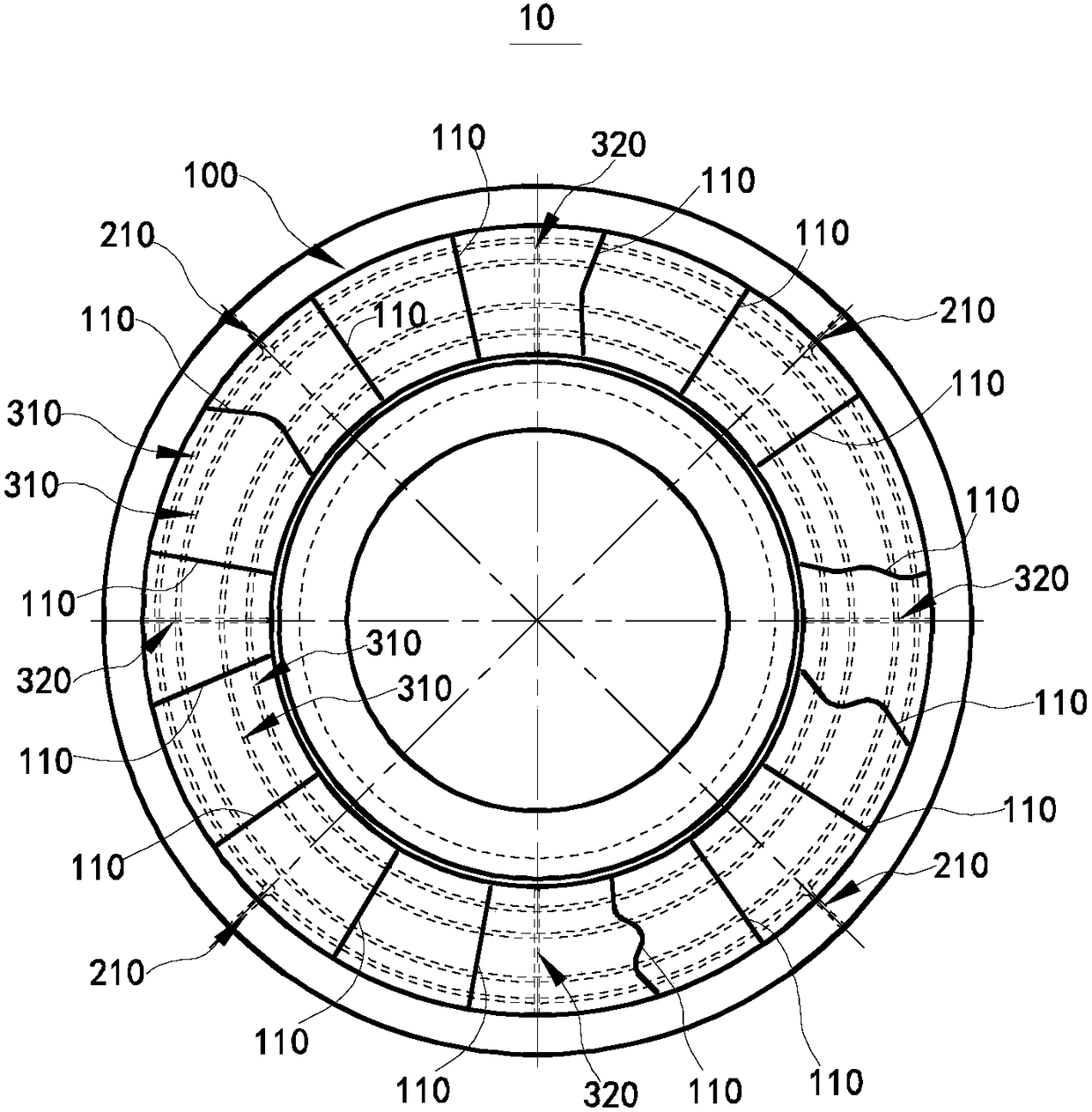
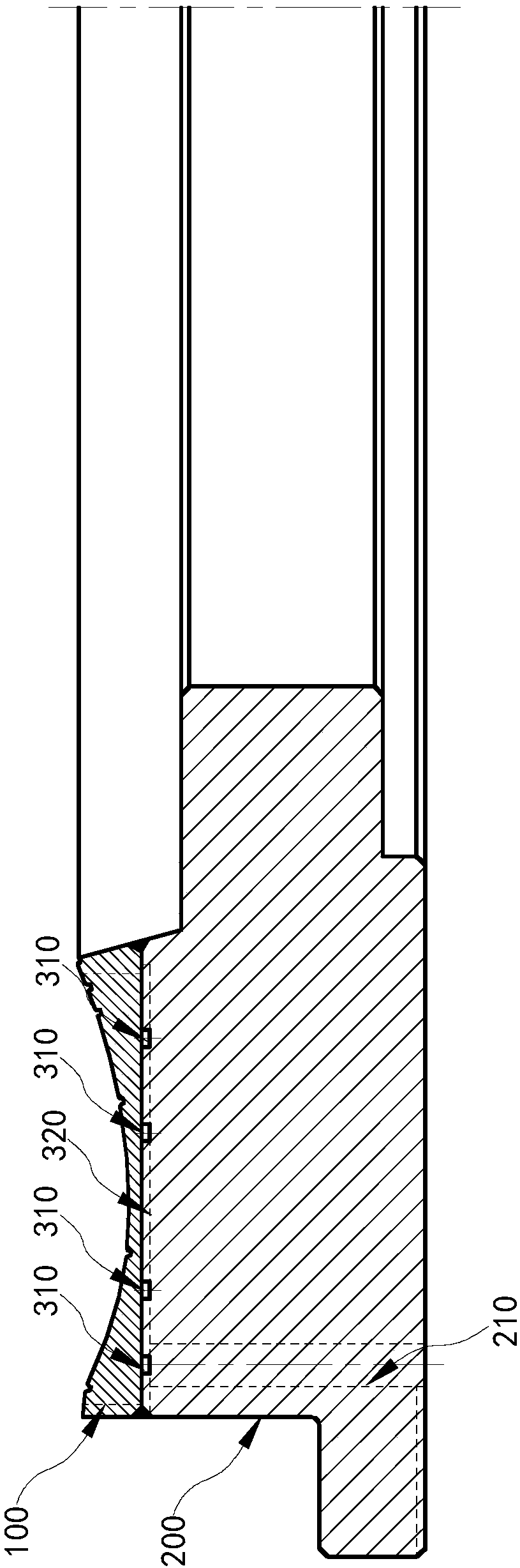
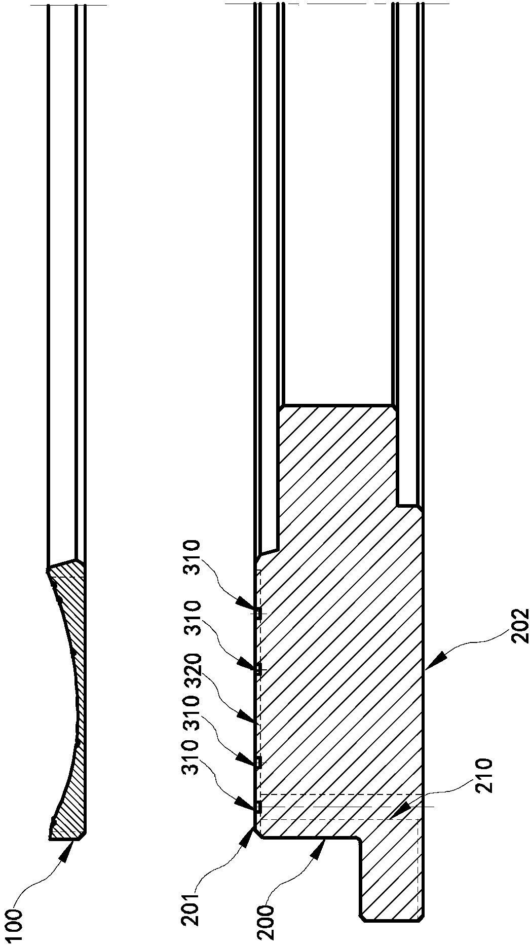
[0065] figure 1 It is a schematic structural diagram of a tire mold side plate 10 provided in an embodiment of the present invention. figure 2 for figure 1 Schematic diagram of the structure from another perspective. image 3 for figure 2 Schematic diagram of the assembly. Please refer to Figure 1-Figure 3 , a tire mold side panel 10 can be seen from the figure, which includes a cavity panel 100 , a connecting portion 222 and a side panel body 200 .

[0066] The side plate body 200 has an inner side 201 close to the green tire and an outer side 202 away from the green tire;

[0067] The cavity panel 100 is disposed on the inner side surface 201 of the side plate body 200 through the connecting portion 222 ; the cavity panel 100 is provided with an exhaust gap 110 , and the exhaust gap 110 is from the side away from the side plate body 200 to the direction close to the side plate body 200 It runs through the cavity panel 100; the cavity panel 100 is provided with patte...


PUM


Abstract

The invention relates to the field of tire molds, in particular to a tire mold side plate and a tire mold. The tire mold side plate comprises a side plate body, a connecting part and a molding cavitypanel. The side plate body is provided with an inner side surface near a tire blank, and an outer side surface far from the tire blank; the connecting part and the molding cavity panel are arranged onthe inner side surface of the side plate body through the connecting part; an exhaust gap is formed in the molding cavity panel, and penetrates through the molding cavity panel from the side far fromthe side plate body to a direction of approaching the side plate body; the exhaust gap is of a non-through structure; the molding cavity panel on the two sides of the exhaust gap is partially connected; an exhaust channel is formed in the connecting part; one end of the exhaust channel is connected with the exhaust gap; and the other end of the exhaust channel penetrates to the outer side surfaceof the side plate body. The tire mold side plate improves the inconvenience problem caused by discharge of plastic from exhaust holes during exhausting in a traditional tire mold.

Description

technical field [0001] The invention relates to the field of tire molds, and in particular, to a tire mold side plate, a tire mold and a processing method. Background technique [0002] When the tire is vulcanized, the air between the side plate and the tire blank needs to be exhausted during the clamping process of the movable mold. The long-term method is to set the exhaust hole and the exhaust line in the side plate, but the exhaust hole discharges the gas at the same time. It will also discharge the rubber material from the air holes, forming a lot of rubber fuzz on the side of the tire. [0003] There are still the following problems in the side plate with the vent hole: 1. The vulcanized tire is not beautiful. If the tire needs to be trimmed before leaving the factory, it will also increase the labor cost of the tire factory; [0004] 2. The trimmed rubber wool can only be treated as waste, wasting raw materials, and it is difficult to naturally degrade the rubber woo...

Claims


Application Information

Patent Timeline
Patent Type & Authority Applications(China)
IPC IPC(8): B29D30/06B29C35/02B29C33/10
CPCB29D30/0606B29D2030/0617
Inventor 夏世涛王万里葛书花王磊杜平孙日文
Owner HIMILE MECHANICAL SCI & TECH (SHANDONG) CO LTD
Why Eureka
Try Eureka