Supercharge Your Innovation With Domain-Expert AI Agents!

Probe fixing structure for weaving machine

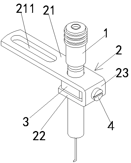
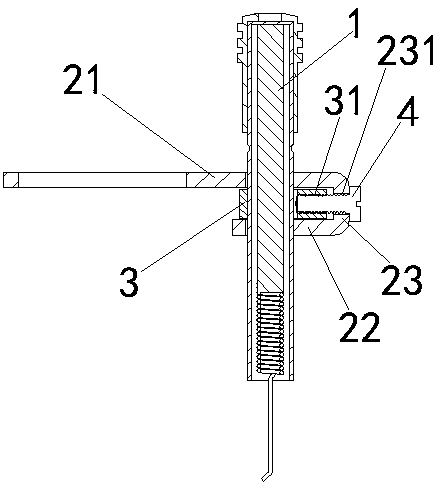
A technology for fixing structures and probes, applied in the directions of knitting, textiles and papermaking, can solve the problems of probe position deviation, probe damage, probe failure, etc., to achieve comprehensive force, improve service life, and fix solid effect

Pending Publication Date: 2018-09-28
JIANGSU RUNSHAN PRECISION MACHINERY TECH CO LTD
View PDF5 Cites 0 Cited by
  • Summary
  • Abstract
  • Description
  • Claims
  • Application Information

AI Technical Summary

Problems solved by technology

[0003] In the equipment, the probe needs to be fixed by a fixing frame, but the existing fixing frame has a simple structure and is rigid. The probe will swing left and right, causing the position of the probe to shift, so that the probe cannot reach the desired position. position, and when the wire is tightened hard, the probe will be dented by the top and the probe will be damaged

Method used


Image

  • Probe fixing structure for weaving machine
  • Probe fixing structure for weaving machine

Examples


Embodiment Construction

[0020] The technical solutions of the present invention will be clearly and completely described below in conjunction with the accompanying drawings. Apparently, the described embodiments are some of the embodiments of the present invention, but not all of them. Based on the embodiments of the present invention, all other embodiments obtained by persons of ordinary skill in the art without making creative efforts belong to the protection scope of the present invention.

[0021] In the description of the present invention, it should be noted that the terms "center", "upper", "lower", "left", "right", "vertical", "horizontal", "inner", "outer" etc. The indicated orientation or positional relationship is based on the orientation or positional relationship shown in the drawings, and is only for the convenience of describing the present invention and simplifying the description, rather than indicating or implying that the referred device or element must have a specific orientation, ...


PUM


Abstract

The invention relates to a probe fixing structure for a weaving machine. The probe fixing structure comprises a fixing shelf, a locating block and a fixing screw, wherein the cross section of the fixing shelf is in a U shape, and the fixing shelf comprises a first slab a second slab which are parallel to each other and a side plate for making the first slab and the second slab connected; the locating block is arranged between the first slab and the second slab, a threaded hole is formed in the side face of the locating block, and a screw through hole is also formed in the side plate; the fixing screw is arranged at the outer side of the side plate, penetrates through the screw through hole and then penetrates into the threaded hole, and is used for adjusting the distance between the locating block and the side plate; the first slab and the second slab are provided with through holes for a probe to penetrate through, a limiting hole is correspondingly formed in the locating block, and the probe penetrates through the through hole in the first slab and then penetrates out of the through hole in the second slab after penetrating through the limiting hole. The probe fixing structure isstable, firm and capable of preventing the probe from being deviated and displaced, and the probe cannot be influenced at the same time.

Description

technical field [0001] The invention relates to the technical field of textile equipment, in particular to a probe fixing structure for a loom. Background technique [0002] When the loom is working, in order to ensure the working stability of the equipment, it is necessary to detect whether the knitting needle is working normally. When the knitting needle latch is opened, the knitting needle hooks the yarn normally; At the probe position, the closed needle latch just touches the probe, at this time the probe light lights up to alarm, and the machine stops. [0003] In the equipment, the probe needs to be fixed by a fixing frame, but the existing fixing frame has a simple structure and is rigid. The probe will swing left and right, causing the position of the probe to shift, so that the probe cannot reach the desired position. position, and when the wire is tightened hard, the probe will be dented by the top and the probe will be damaged. Contents of the invention [000...

Claims


Application Information

Patent Timeline
IPC IPC(8): D04B35/18
CPCD04B35/18
Inventor 郑泽山李金池
Owner JIANGSU RUNSHAN PRECISION MACHINERY TECH CO LTD
Features
  • R&D
  • Intellectual Property
  • Life Sciences
  • Materials
  • Tech Scout
  • Unparalleled Data Quality
  • Higher Quality Content
  • 60% Fewer Hallucinations
Learn More