
Novel water supply and drainage grating device

A grid, a new type of technology, applied in water supply devices, drainage structures, grease/oily substances/floating matter removal devices, etc., can solve the problems of inability to adjust the gap of the grid bars, low cost, etc. The effect of easy mass production

Pending Publication Date: 2018-09-28
LIAONING UNIVERSITY OF PETROLEUM AND CHEMICAL TECHNOLOGY
View PDF4 Cites 0 Cited by
  • Summary
  • Abstract
  • Description
  • Claims
  • Application Information

AI Technical Summary

Problems solved by technology

Solve the problem in the prior art that the grid gap cannot be adjusted, and the cost of the invention is relatively low

Method used


Image

  • Novel water supply and drainage grating device

Examples


Embodiment

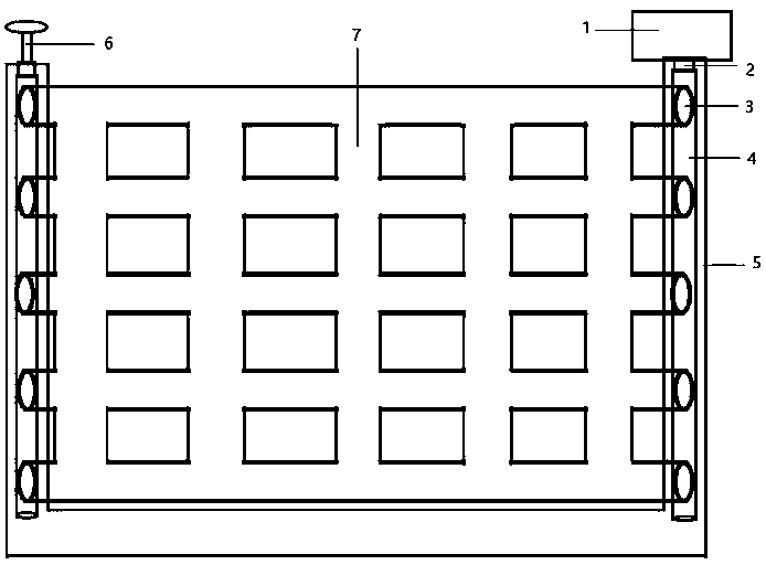
[0017] Such as figure 1 , as shown, including 1, booster air pump 2, connector 3, grid valve 4, buffer chamber 5, metal frame 6, exhaust valve 7, rubber grid. 5. When in use, connect and fix the metal frame with the snap-fit ​​of the fluid pipeline. Turn on 1, the booster air pump to transport the gas to 4, the buffer chamber through the 2, connector, and then act on the 7, rubber grid through the 3, grid valve, and the rubber grid expands under force, making the grid gap smaller. During decompression, the gas in the rubber grating is discharged by opening 6, exhaust valve 7, and 7, the rubber grating restores the original size, so that the gap of the grating becomes larger.

[0018] The advantages and effects of the present invention are as follows: the present invention is by arranging the pressurized pipe section, the grid pipe section, and the exhaust pipe section, and the gas is passed in and out by the pressurized pipe section or the exhaust pipe section. Good ductilit...


PUM


Abstract

The invention discloses a novel water supply and drainage grating device. By arrangement of pressurizing pipe sections, grid pipe sections and exhaust pipe sections, air flows into and out of rubber grid bars through the pressurizing pipe sections or the exhaust pipe sections. Due to high ductility of the rubber grid bars, grid bar gap size can be changed when internal pressure changes, and accordingly gratings variable in thickness can be obtained.

Description

technical field [0001] The invention relates to the technical field of water supply and drainage equipment, in particular to a novel water supply and drainage grille device. Background technique [0002] At present, the grid devices used at home and abroad are mainly used in the sewage pretreatment section to intercept the suspended solids in the sewage and protect the equipment and pipelines of the subsequent process. Among them, according to the size of the grid gap, it can be divided into coarse grid and fine grid. However, there are few grill devices on the market that can adjust the size of the grille. Contents of the invention [0003] The present invention provides a novel grille device aiming at the above-mentioned problems in the prior art. The problem in the prior art that the gaps of grid bars cannot be adjusted is solved, and the cost of the invention is low. [0004] Technical scheme of the present invention is as follows: [0005] Including the pressurize...

Claims


Application Information

Patent Timeline
Patent Type & Authority Applications(China)
IPC IPC(8): E03F5/14
CPCE03F5/14
Inventor 田葳陈佳钰李卓霍昊忱李翀高天一徐宏伟郭杨张艺凡田玉婷马赫美李航任
Owner LIAONING UNIVERSITY OF PETROLEUM AND CHEMICAL TECHNOLOGY
Learn More