
Internally reinforced square pipe column body joint and installation method thereof

A reinforced and reinforced pipe technology, applied in the direction of building maintenance, construction, building structure, etc., can solve the problems of inability to strengthen the joint strength, large restrictions, and inability to install external reinforced pipes.

Inactive Publication Date: 2018-09-28
XINCHANG SICHUANG DESIGN CONSULTING CO LTD
View PDF0 Cites 2 Cited by
  • Summary
  • Abstract
  • Description
  • Claims
  • Application Information

AI Technical Summary

Problems solved by technology

[0002] In the steel structure buildings that are widely used at present, it is usually necessary to install the beam body on the side of the column. If the column is a closed member such as a square tube, a square tubular external reinforcing tube is generally placed on the outside of the column to strengthen the structure of the node. , during construction, fixing the end of the beam body on the external reinforcing tube can significantly improve the beam-column connection structure, but the external reinforcing tube on the outside of the column is limited by the column itself. Set the external reinforcing tube, or only cut the middle of the cylinder, and then insert the external reinforcing tube, which can not play the role of strengthening the joint strength, and the joint is easy to be damaged, so it is necessary to improve

Method used


Image

  • Internally reinforced square pipe column body joint and installation method thereof
  • Internally reinforced square pipe column body joint and installation method thereof
  • Internally reinforced square pipe column body joint and installation method thereof

Examples


Embodiment Construction

[0032] The following are specific embodiments of the present invention and in conjunction with the accompanying drawings, the technical solutions of the present invention are further described, but the present invention is not limited to these embodiments.

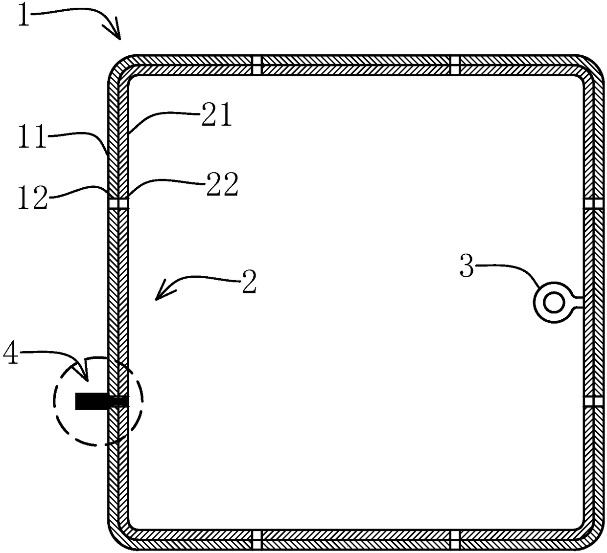
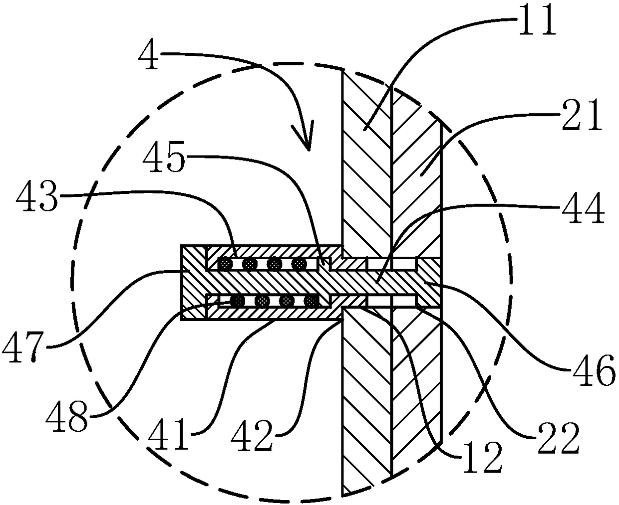
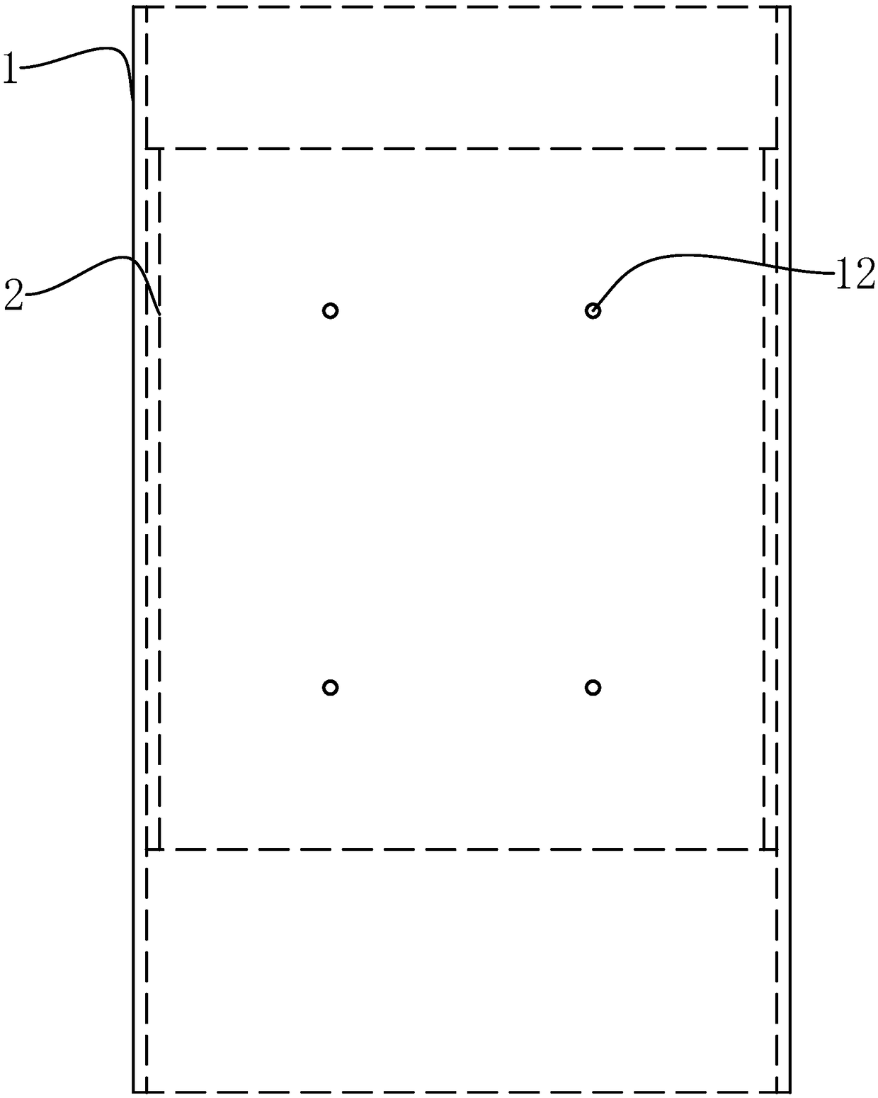
[0033] Such as Figure 1-3 As shown, an internally reinforced square tube column node of the present invention includes a square tubular column body 1, the column body 1 includes four column plates 11, and also includes a square tubular inner reinforcing tube 2 embedded in the column body 1, The column body 1 fits on the outside of the inner reinforcing tube 2, the inner reinforcing tube 2 includes four inner reinforcing plates 21, and the outer side of the inner reinforcing plate 21 is attached to the inner side of the column plate 11, and the inner side of the inner reinforcing plate 21 is fixed with a suspension ring 3 , the column plate 11 is provided with some threaded connecting holes 12, and the inner reinforcing pl...


PUM


Abstract

The invention provides an internally reinforced square pipe column body joint and an installation method thereof, and belongs to the field of steel structures. According to the internally reinforced square pipe column body joint and the installation method thereof, the problem of low strength of existing square pipe column body joints is solved. The internally reinforced square pipe column body joint comprises a column body, a square-pipe-shaped internally reinforced pipe, a locating piece and a compression spring. The column body comprises four column plates, and the square-pipe-shaped internally reinforced pipe is embedded in the column body in a matched mode. The internally reinforced pipe is sleeved with the column body in a matched mode, the internally reinforced pipe comprises four internally reinforced plates, and a lifting ring is fixed to the inner side face of one of the internally reinforced plates. A plurality of connecting holes are formed in the column plates, and a plurality of reinforced holes are formed in the internally reinforced plates. The locating piece comprises a locating rod and a locating pipe, wherein the locating rod is sleeved with the locating pipe, anexternal thread is arranged on the outer wall of the front end of the locating pipe, the front end of the locating pipe is connected to the outer end of one of the connecting holes in a threaded mode, and a spring groove is formed in the inner wall of the locating pipe. A moving block is arranged on the rod wall of the locating rod, and the locating rod is sleeved with the compression spring. Theinternally reinforced square pipe column body joint can achieve later reinforcement.

Description

technical field [0001] The invention belongs to the technical field of steel structures, and relates to an internally reinforced square tube cylinder node and an installation method thereof. Background technique [0002] In the steel structure buildings that are widely used at present, it is usually necessary to install the beam body on the side of the column. If the column is a closed member such as a square tube, a square tubular external reinforcing tube is generally placed on the outside of the column to strengthen the structure of the node. , during construction, fixing the end of the beam body on the external reinforcing tube can significantly improve the beam-column connection structure, but the external reinforcing tube on the outside of the column is limited by the column itself. Putting the external reinforcing tube, or only cutting the middle of the cylinder, and then inserting the external reinforcing tube can not play the role of strengthening the strength of th...

Claims


Application Information

Patent Timeline
IPC IPC(8): E04G23/02E04B1/24E04B1/58
CPCE04G23/0218E04B1/2403E04B2001/2406
Inventor 黄士玉
Owner XINCHANG SICHUANG DESIGN CONSULTING CO LTD
Learn More