A foundation pit support system and its construction method used in expansive soil areas
A technology of foundation pit support and expansive soil, which is applied in the direction of foundation structure engineering, excavation, construction, etc., can solve the problems of expansive soil foundation pits being flooded by rainfall and increased expansion force, etc., to enhance the strength of nodes and connections, and reduce loads , Enhance the effect of supporting ability
- Summary
- Abstract
- Description
- Claims
- Application Information
AI Technical Summary
Problems solved by technology
Method used
Image
Examples
Embodiment 1
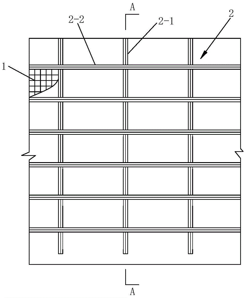
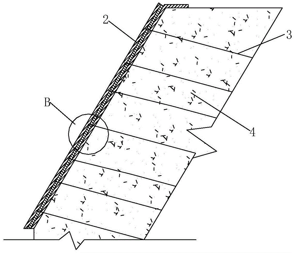
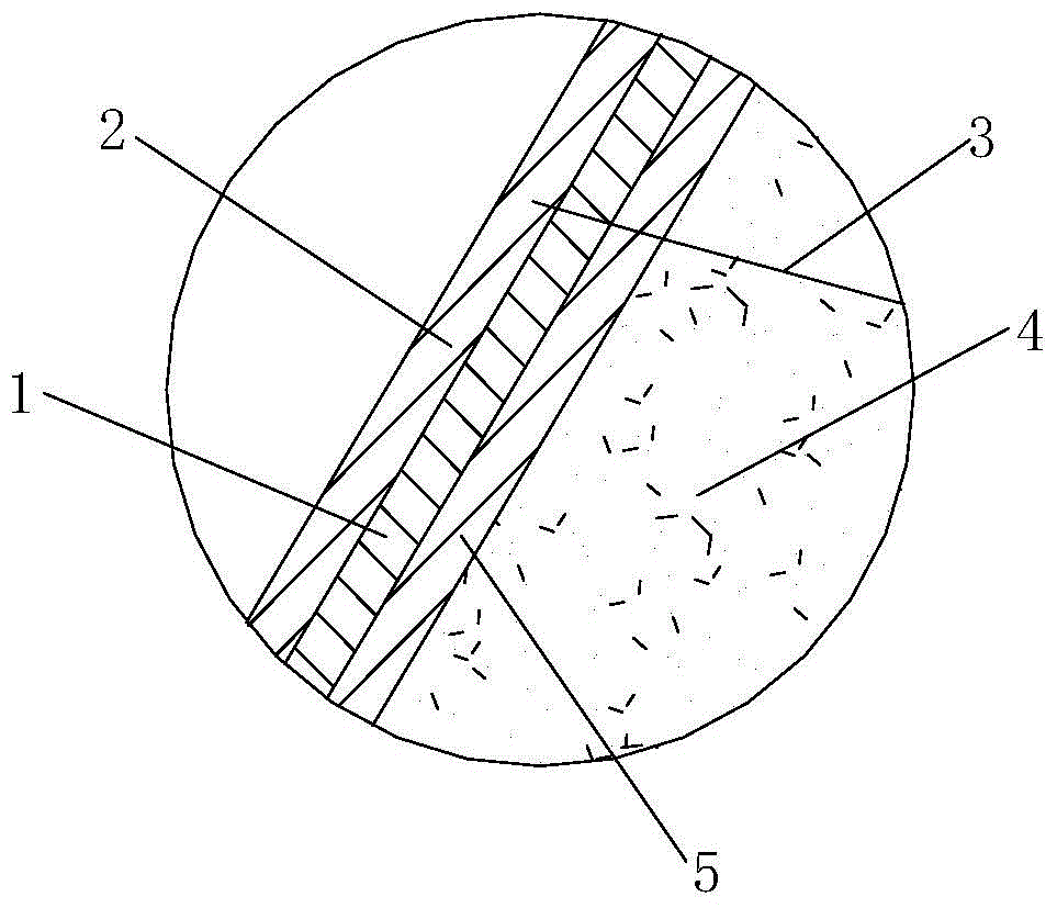
[0051] like figure 1 , figure 2 , image 3 and Figure 4 A foundation pit supporting system shown in the expansive soil area includes a flexible anti-seepage layer 5 laid on the foundation pit slope 4 and a restraint layer 2 laid on the flexible anti-seepage layer 5, the The restraint layer 2 is composed of a plurality of longitudinal restraint belts 2-1 and a plurality of transverse restraint belts 2-2 interlaced. The flexible anti-seepage layer 5 and the soil nails 3 extending into the slope 4 of the foundation pit.
[0052] In this embodiment, the soil nail 3 and the flexible anti-seepage layer 5 are connected together through the bound layer 2, and the earth pressure generated by the foundation pit slope 4 is transmitted to the bound layer 2 through the flexible anti-seepage layer 5, and then transmitted by the bound layer 2 Give the soil nail 3, and then transfer it to the soil layer beyond the sliding surface by the soil nail 3. By setting a layer of flexible anti-...
Embodiment 2
[0065] like Figure 5 As shown, the difference between this embodiment and Embodiment 1 is that the foundation pit support system for expansive soil areas also includes horizontally arranged along the foundation pit slope 4 and pressed on the longitudinal restraint belt 2-1 The steel beams 7 and the lattice beams 11 vertically arranged along the slope 4 of the foundation pit and pressed on the transverse restraint belt 2-2. The steel beam 7 is formed by splicing two parallel shaped steels 7-1. The lattice beam 11 is a reinforced concrete beam.
[0066] like Figure 6 and Figure 7 As shown, an anchor rod 6 is arranged between the two section steels 7-1, and one end of the anchor rod 6 passes through the longitudinal restraint belt 2-1, the steel mesh 1 and the flexible anti-seepage layer 5 sequentially and extends into the The slope 4 of the foundation pit, the other end of the anchor rod 6 passes through between the two shaped steels 7-1 and passes through the wedge-shape...
PUM
 Abstract
Description
Claims
Application Information
 - R&D
- Intellectual Property
- Life Sciences
- Materials
- Tech Scout
- Unparalleled Data Quality
- Higher Quality Content
- 60% Fewer Hallucinations
Browse by: Latest US Patents, China's latest patents, Technical Efficacy Thesaurus, Application Domain, Technology Topic, Popular Technical Reports.
© 2025 PatSnap. All rights reserved.Legal|Privacy policy|Modern Slavery Act Transparency Statement|Sitemap|About US| Contact US: help@patsnap.com


