Viscous crude oil viscosity reduction emulsification treatment equipment

A technology for emulsification and crude oil, which is applied in wellbore/well components, production fluids, and earth-moving drilling, etc. It can solve the problems of controlling the input amount of viscosity reducer, unable to realize re-mixing, etc., to reduce flow resistance and inclination. Angle, the effect of reducing oil viscosity

Active Publication Date: 2019-07-12
山东天厚石油科技有限责任公司
View PDF1 Cites 0 Cited by
  • Summary
  • Abstract
  • Description
  • Claims
  • Application Information

AI Technical Summary

Problems solved by technology

This invention uses a viscosity reducer to replace part of the thin oil through a simple process modification, which greatly reduces the production cost of super heavy oil, but this invention cannot control the input amount of the viscosity reducer according to the viscosity of the oil, and cannot achieve a higher viscosity. Large oil return to remix with emulsifier or viscosity reducer

Method used


Image

  • Viscous crude oil viscosity reduction emulsification treatment equipment
  • Viscous crude oil viscosity reduction emulsification treatment equipment
  • Viscous crude oil viscosity reduction emulsification treatment equipment

Examples


specific Embodiment approach 1

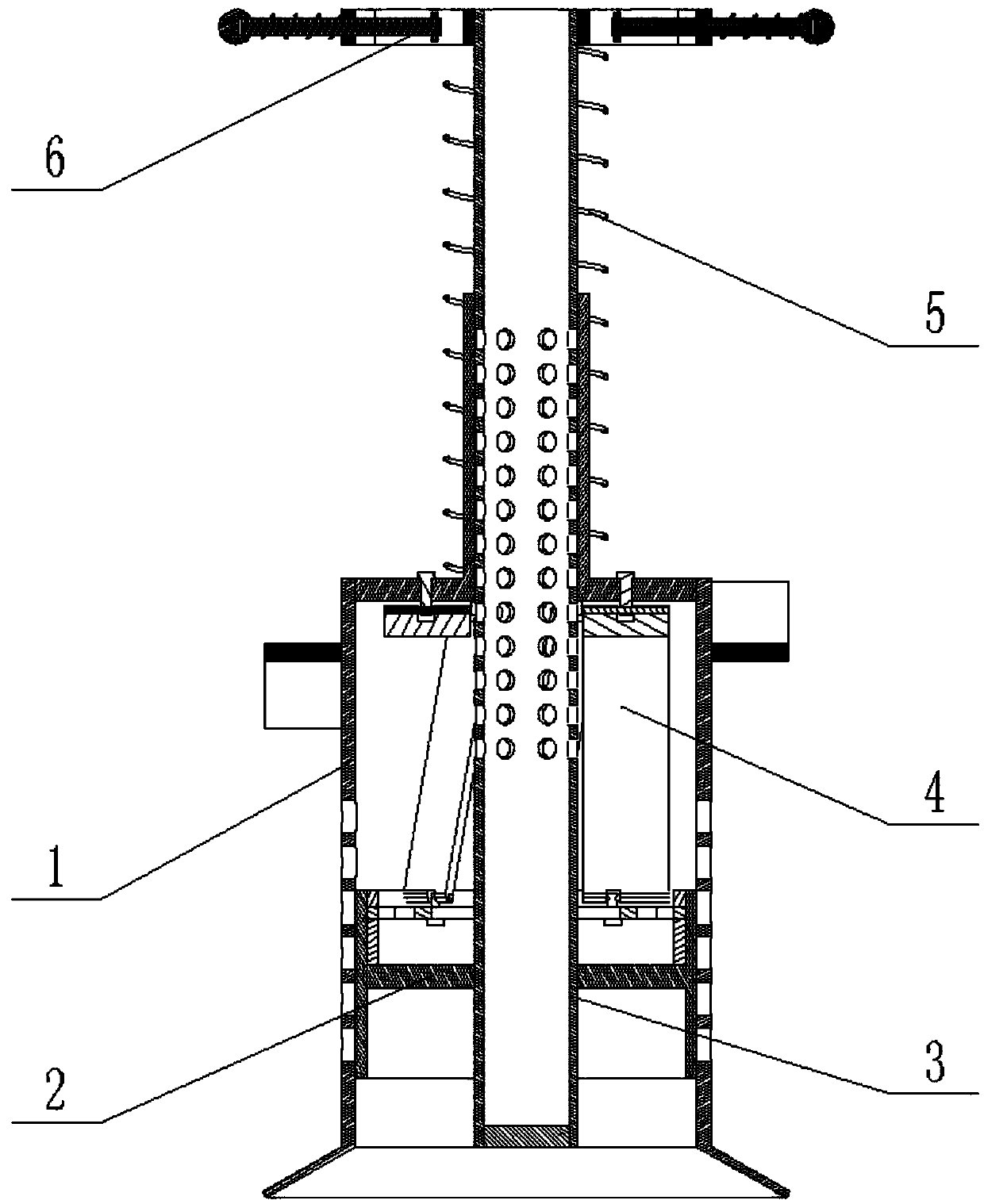
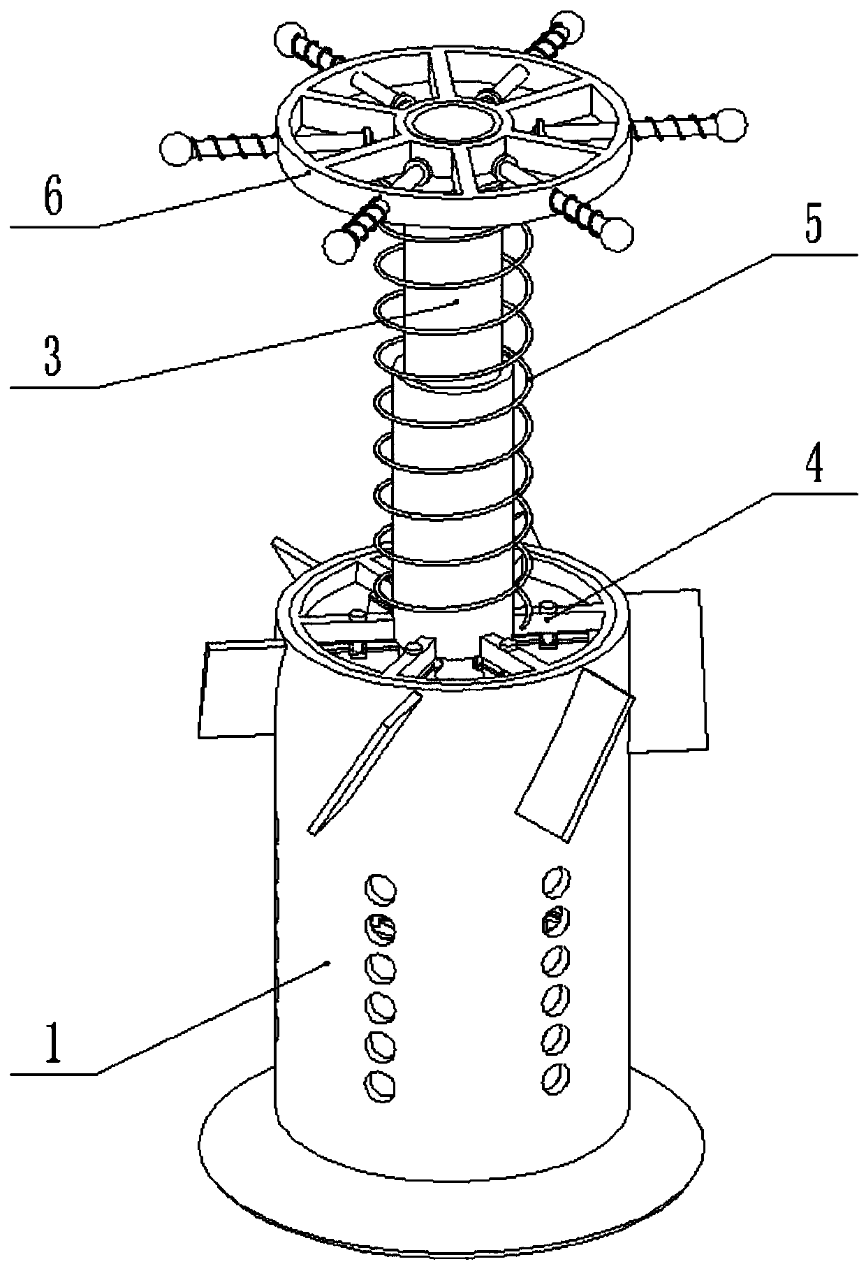
[0031] Combine below Figure 1-10 Description of this embodiment, viscous crude oil viscosity reduction emulsification treatment equipment, including stirring sleeve 1, oil sealing sleeve 2, viscosity reducing agent delivery pipe 3, internal rotation assembly 4, spring 5 and fixing device 6, the oil sealing sleeve 2 Slidingly connected in the stirring sleeve 1, the oil sealing sleeve 2 is fixedly connected to the viscosity reducing agent delivery pipe 3, the lower end of the internal rotation assembly 4 is connected to the oil sealing sleeve 2 in rotation, the middle of the internal rotation assembly 4 The end is fixedly connected to the stirring sleeve 1, the internal rotation assembly 4 is slidably connected to the viscosity reducer delivery pipe 3, the fixing device 6 is fixedly connected to the upper end of the viscosity reducer delivery pipe 3, and the spring 5 is set inside Between the screw assembly 4 and the fixing device 6; when in use, the viscous crude oil viscosity...

specific Embodiment approach 2

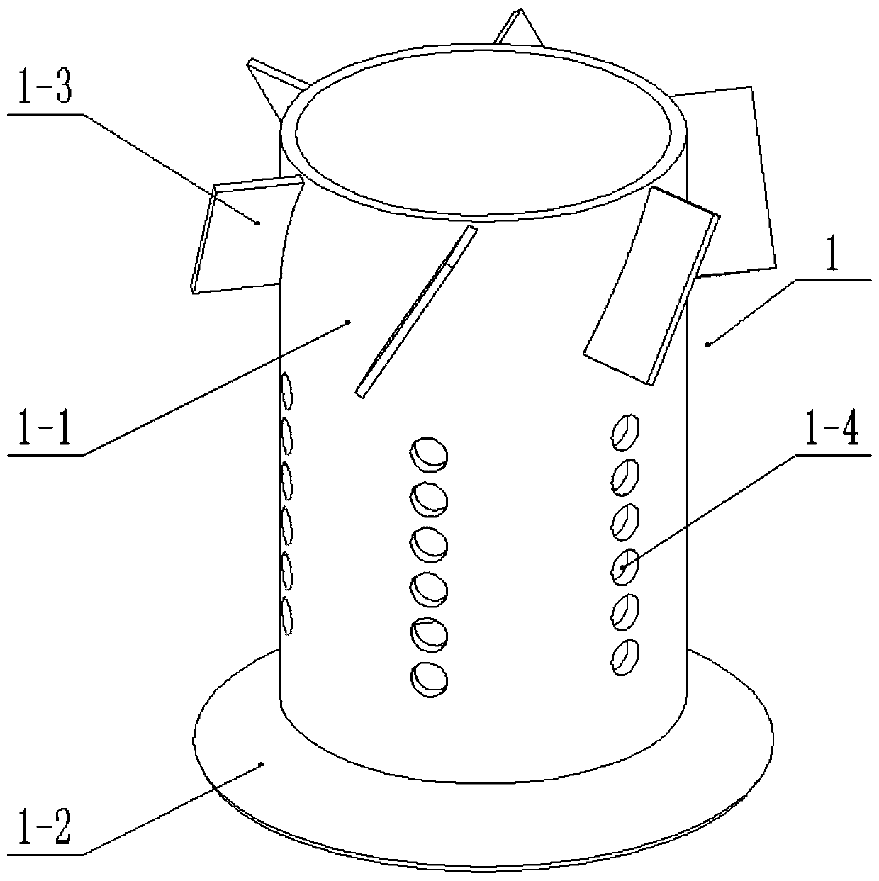
[0033] Combine below Figure 1-10 Describe this embodiment, this embodiment will further explain the first embodiment, the stirring sleeve 1 includes a sleeve 1-1, a cone bucket 1-2, a plurality of return blades 1-3 and a plurality of return holes 1-4, so The cone bucket 1-2 is fixedly connected to the lower end of the sleeve 1-1, and the outside of the upper end of the sleeve 1-1 is evenly and fixedly connected with a plurality of return vanes 1-3, and the middle end of the sleeve 1-1 is provided with A plurality of reflux holes 1-4 evenly distributed in the radial direction, the oil flow drives the internal rotation component 4 to rotate, and the rotation of the internal rotation component 4 drives the stirring sleeve 1 to rotate, and the stirring sleeve 1 rotates through multiple return blades 1-3 to make the stirring The oil at the upper end of the sleeve 1 flows downward through the outside of the sleeve 1-1, and finally flows into the sleeve 1-1 through a plurality of re...

specific Embodiment approach 3

[0035] Combine below Figure 1-10Describe this embodiment, this embodiment will further explain Embodiment 2, the oil seal sleeve 2 includes an oil seal ring 2-1, an oil seal inner connection sleeve 2-2, a support ring 2-3 and a retaining ring 2-4 , the oil sealing inner connecting sleeve 2-2 is fixedly connected inside the oil sealing ring 2-1, the oil sealing ring 2-1 is slidingly connected inside the sleeve 1-1, and the oil sealing inner connecting sleeve 2 -2 is fixedly connected to the viscosity reducer delivery pipe 3, the support ring 2-3 is fit in the oil sealing ring 2-1, and the support ring 2-3 is located at the upper end of the oil sealing inner connecting sleeve 2-2, The retaining ring 2-4 is fixedly connected to the inner upper end of the oil sealing ring 2-1; the oil sealing ring 2-1 blocks part of the return hole 1-4 located at the lower end, and when the stirring sleeve 1 slides upward, it is connected to the sleeve The number of return holes 1-4 inside the s...


PUM


Abstract

The invention relates to the technical field of crude oil viscosity reduction treatment, in particular to emulsification treatment equipment for medium viscous crude oil viscosity reduction. The emulsification treatment equipment comprises a stirring sleeve, an oil sealing sleeve, a viscosity reducer conveying pipe, an internal rotation assembly, a spring and a fixing device. The oil sealing sleeve is slidably connected into the stirring sleeve and fixedly connected to the viscosity reducer conveying pipe, and the lower end of the internal rotation assembly is rotationally connected to the oilsealing sleeve. The middle end of the internal rotation assembly is fixedly connected to the stirring sleeve, and the internal rotation assembly is slidably connected to the viscosity reducer conveying pipe. The fixing device is fixedly connected to the upper end of the viscosity reducer conveying pipe, and the spring is arranged between the internal rotation assembly and the fixing device. The emulsification treatment equipment can rotate during oil liquid flowing, and oil liquid is mixed with an emulsifier or an viscosity reducer advantageously; and the conveying flow rate of the emulsifieror the viscosity reducer can be increased when the viscosity of the oil liquid is large, the backflow proportion of the oil liquid is increased, the inclination angle of inner stirring blades can bedecreased, and flowing resistance of the oil liquid is reduced.

Description

technical field [0001] The invention relates to the technical field of crude oil viscosity reduction treatment, in particular to emulsification treatment equipment for viscous crude oil viscosity reduction. Background technique [0002] For example, the patent application number is CN201210537149.4, a method and equipment suitable for super heavy oil recovery. The method includes injecting a mixture of thin oil and viscosity reducer into the bottom of the oil well, mixing it with heavy oil, and then extracting the oil. operate. Its equipment includes intersecting thin oil pipelines (3) and viscosity reducer pipelines connected with drug storage tanks (1) and metering pumps (2), and the intersected pipelines are sequentially connected to ground mixers (5) and oil well casings ( 6) The annular space. This invention uses a viscosity reducer to replace part of the thin oil through a simple process modification, which greatly reduces the production cost of super heavy oil, but ...

Claims


Application Information

Patent Timeline
Patent Type & Authority Patents(China)
IPC IPC(8): E21B43/22
CPCE21B43/16
Inventor 王玉莲
Owner 山东天厚石油科技有限责任公司
Why Eureka
Try Eureka