Power transmission device and disassembly method

A technology of power transmission device and reducer, which is applied in the direction of elastic coupling, mechanical equipment, coupling, etc., can solve problems such as time-consuming, affecting production efficiency, and costing a lot of manpower and time, so as to reduce personnel safety risks , replacement and maintenance time is short, the effect of improving production efficiency

Pending Publication Date: 2018-09-28
BEIJING XUANYU INTELLIGENT TECH CO LTD
View PDF8 Cites 1 Cited by
  • Summary
  • Abstract
  • Description
  • Claims
  • Application Information

AI Technical Summary

Problems solved by technology

[0002] The existing power transmission device usually consists of an integral coupling directly connected to the reducer and the motor in series, and then the connection is fastened and fixed by screws. When maintaining and replacing components, it is necessary to disassemble the fastening on the coupling and the reducer one by one. Screws require a lot of manpower and time, especially in the hot chamber, because the operator can only perform loading and unloading operations through the remote robotic arm, and the remote robotic arm can usually only perform simple actions such as clamping and opening. It is impossible to flexibly twist the screws, so the only way for the staff to wear radiation protection equipment is to enter the hot chamber for loading and unloading, and the heavy gloves still greatly hinder the staff's loading and unloading work, not to mention that the staff can only stay in the hot chamber Limited time, therefore, even if the staff enters the hot chamber for loading and unloading operations, it often takes a lot of time, which affects production efficiency. At the same time, the staff entering the hot chamber also has a greater safety hazard

Method used


Image

  • Power transmission device and disassembly method
  • Power transmission device and disassembly method
  • Power transmission device and disassembly method

Examples


Embodiment Construction

[0025] The following description and drawings illustrate specific embodiments of the invention sufficiently to enable those skilled in the art to practice them. The examples merely represent possible variations. Individual components and functions are optional unless explicitly required, and the order of operations may vary. Portions and features of some embodiments may be included in or substituted for those of other embodiments. The scope of embodiments of the present invention includes the full scope of the claims, and all available equivalents of the claims.

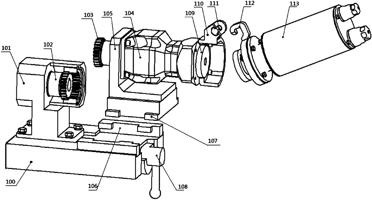
[0026] According to the first aspect of the embodiments of the present invention, a power transmission device that can be quickly installed and disassembled is provided, figure 1 It is a schematic structural diagram of a ready-to-assemble state of an embodiment of the power transmission device according to the present invention. Such as figure 1 As shown, the power transmission device includes a base 100 , a gear...


PUM


Abstract

The invention discloses a power transmission device. The power transmission device comprises a base, a gear coupling, a speed reducer and a motor; the gear coupling comprises a first gear module and asecond gear module coaxially engaged through a connecting inner gear ring; the first gear module is fixed on one side of the top surface of the base; the second gear module is fixed at one end of thespeed reducer; a clamping groove is formed in the other side of the base; the speed reducer comprises a speed reducer body and a stand; a convex block cooperating with the clamping groove is arrangedat the bottom of the stand; and the end, far from the gear coupling, of the speed reducer is fixedly connected with the motor. The invention further provides a disassembly method of the power transmission device. The power transmission device can simply and conveniently replace the motor and the speed reducer without needing staff to enter a heat chamber, greatly reduces the personal safety risk,guarantees the personal safety, is short in replacement and maintenance time, and improves the production efficiency.

Description

technical field [0001] The invention relates to a power transmission device, in particular to a power transmission device that can be quickly assembled and disassembled and a disassembly method. Background technique [0002] The existing power transmission device usually consists of an integral coupling directly connected to the reducer and the motor in series, and then the connection is fastened and fixed by screws. When maintaining and replacing components, it is necessary to disassemble the fastening on the coupling and the reducer one by one. Screws require a lot of manpower and time, especially in the hot chamber, because the operator can only perform loading and unloading operations through the remote robotic arm, and the remote robotic arm can usually only perform simple actions such as clamping and opening. It is impossible to flexibly twist the screws, so the only way for the staff to wear radiation protection equipment is to enter the hot chamber for loading and un...

Claims


Application Information

Patent Timeline
Patent Type & Authority Applications(China)
IPC IPC(8): F16D3/18F16D3/16
CPCF16D3/16F16D3/18
Inventor 李建营张韬懿尹文彬冀会忠
Owner BEIJING XUANYU INTELLIGENT TECH CO LTD
Why Eureka
Try Eureka