
Safety valve plate buffer mechanism

A technology of buffer mechanism and safety valve, applied in sliding valve, valve details, valve device and other directions, can solve the problems of limited service life, deformation of valve plate, weak resistance to impact force of valve plate, etc.

Inactive Publication Date: 2018-09-28
中山达鼎精密工业有限公司
View PDF0 Cites 1 Cited by
  • Summary
  • Abstract
  • Description
  • Claims
  • Application Information

AI Technical Summary

Problems solved by technology

[0002] The valve plate of the safety valve in the prior art is used for a long time, which easily causes the deformation of the valve plate, the impact resistance of the valve plate is weak, and the service life is limited; the valve plate of the safety valve in the prior art cannot block the impact of the water flow, which increases the valve The plate bears pressure, so there is an urgent need for a safety valve plate buffer mechanism to solve the above problems

Method used


Image

  • Safety valve plate buffer mechanism
  • Safety valve plate buffer mechanism
  • Safety valve plate buffer mechanism

Examples


Embodiment Construction

[0018] In order to make the technical means, creative features, goals and effects achieved by the present invention easy to understand, the present invention will be further described below in conjunction with specific embodiments.

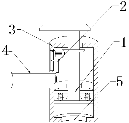
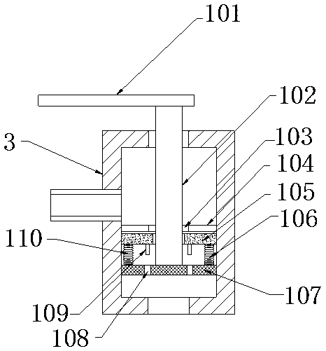
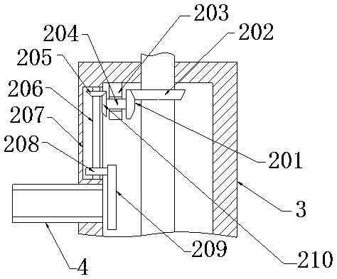
[0019] see Figure 1-Figure 3 , the present invention provides a technical solution: a safety valve plate buffer mechanism, including a valve body 3, a water inlet pipe 4, a water outlet 5, a buffer assembly 1 and an auxiliary sealing assembly 2, and the water inlet pipe 4 is arranged on the valve body 3 in an annular On the left side of the side, the water outlet 5 is set in the middle of the lower end of the valve body 3, and the buffer assembly 1 is arranged in the middle of the valve body 3. The buffer assembly 1 includes a valve handle 101, a screw rod 102, a nut seat 103, and a valve plate Body 104, rubber pad 105, right spring 106, carrier plate 107, leak hole 108, sealing plug 109 and left spring 110, auxiliary sealing assembly 2 is arrang...


PUM


Abstract

The invention provides a safety valve plate buffer mechanism. The safety valve plate buffer mechanism comprises a valve body, a water inlet pipe, a water outlet, a buffer module and an auxiliary blockage module; the water inlet pipe is arranged at the left part of the annular side surface of the valve body; the water outlet is formed in the middle part of the lower end surface of the valve body; the buffer module is arranged at the middle part in the valve body; the buffer module comprises a valve handle, a first lead screw, a first nut base, a valve plate body, a rubber pad, a right spring, acarrier plate, a water leakage hole, a sealing plug and a left spring; the auxiliary blockage module is arranged on the left side of the upper part in the valve body; and the auxiliary blockage module comprises a first bevel gear, a second bevel gear, a base, a connecting rod, a third bevel gear, a second lead screw, a guide groove, a second nut base, a sealing plate and a fourth bevel gear. Compared with the prior art, the safety valve plate buffer mechanism has the beneficial effects of achieving the buffer function of a valve plate body and achieving the blockage function of the water inlet pipe.

Description

technical field [0001] The invention relates to a buffer mechanism for a valve plate of a safety valve, which belongs to the technical field of valves. Background technique [0002] The valve plate of the safety valve in the prior art is used for a long time, which easily causes the deformation of the valve plate, the impact resistance of the valve plate is weak, and the service life is limited; the valve plate of the safety valve in the prior art cannot block the impact of the water flow, which increases the valve The plate bears pressure, so a safety valve plate cushioning mechanism is urgently needed to solve the above-mentioned problems. Contents of the invention [0003] Aiming at the deficiencies in the prior art, the object of the present invention is to provide a safety valve plate buffer mechanism to solve the problems raised in the above-mentioned background technology. The present invention is easy to use, easy to operate, good in stability and high in reliabili...

Claims


Application Information

Patent Timeline
IPC IPC(8): F16K3/00F16K31/50F16K31/53F16K3/30F16F15/04
CPCF16K3/00F16F15/04F16K3/30F16K31/508F16K31/53
Inventor 陈达明高应鹏徐勇亮
Owner 中山达鼎精密工业有限公司
Learn More