
Optical cable circuit fault positioning and detection method and terminal equipment

A technology for line faults and detection methods, which is used in testing optical fiber/optical waveguide equipment, optical instrument testing, and measuring devices, etc., can solve problems such as low work efficiency, labor and material resources, inconsistent damage standards, etc., to improve accuracy. and efficiency, to achieve the effect of intelligent recognition

Active Publication Date: 2018-09-28
STATE GRID CORP OF CHINA +1
View PDF8 Cites 24 Cited by
  • Summary
  • Abstract
  • Description
  • Claims
  • Application Information

AI Technical Summary

Problems solved by technology

[0004] In view of this, the embodiment of the present invention provides a method for locating and detecting a fault in an optical cable line and a terminal device to solve the problem that in the prior art, the judgment of the inspectors is very subjective, the standards for the judgment of the damage are inconsistent, and the work efficiency is low. , a problem that consumes a lot of manpower and material resources

Method used


Image

  • Optical cable circuit fault positioning and detection method and terminal equipment
  • Optical cable circuit fault positioning and detection method and terminal equipment
  • Optical cable circuit fault positioning and detection method and terminal equipment

Examples


Embodiment Construction

[0050] In the following description, specific details such as specific system structures and technologies are presented for the purpose of illustration rather than limitation, so as to thoroughly understand the embodiments of the present invention. It will be apparent, however, to one skilled in the art that the invention may be practiced in other embodiments without these specific details. In other instances, detailed descriptions of well-known systems, devices, circuits, and methods are omitted so as not to obscure the description of the present invention with unnecessary detail.

[0051] In order to illustrate the technical solutions of the present invention, specific examples are used below to illustrate.

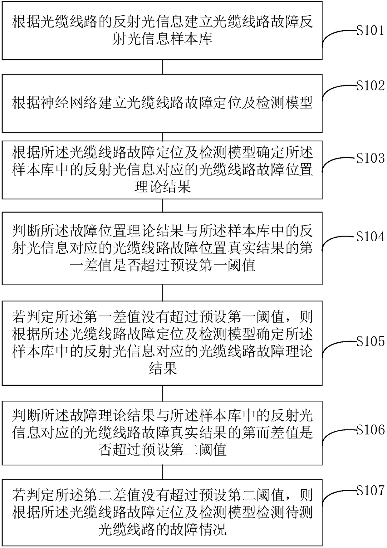
[0052] Such as figure 1 As shown, it is a flow chart of the steps of an optical cable line fault location and detection method provided by an embodiment of the present invention, including:

[0053] In step S101, a sample database of reflected light information of a fau...


PUM


Abstract

The invention is applicable to the technical field of optical cable detection, and provides an optical cable circuit fault positioning and detection method and terminal equipment. The method includesthe following steps: establishing an optical cable circuit fault reflected light information sample library according to the reflected light information; establishing an optical cable circuit fault positioning and detection model according to a neural network; determining the theoretical result of the fault position of the optical cable circuit corresponding to the reflected light information in the sample library; judging whether a first difference value of the fault position theoretical result and the optical cable circuit fault position true result corresponding to the reflected light information exceeds a preset first threshold value or not; determining the fault theoretical result if the judgment does not exceed the preset first threshold value; judging whether the second difference value of the fault theoretical result and the fault true result of the optical cable circuit exceeds a preset second threshold value or not; detecting the fault condition of the optical cable circuit to be tested if the judgment does not exceed the preset second threshold value. By adopting the scheme, the accuracy of the fault identification of the optical cable circuit is improved, and the intelligent identification of the fault of the optical cable circuit is realized.

Description

technical field [0001] The invention belongs to the technical field of optical cable detection, and in particular relates to an optical cable line fault location and detection method and terminal equipment. Background technique [0002] With the expansion of the construction scale of my country's communication optical cable lines, and the aging phenomenon of established optical cable lines over time, the possibility of failure of optical cable lines is increasing, and the direct economic losses caused by the interruption of optical cable lines are increasing every year. More and more, the losses caused to the national economy and national defense communications are also staggering. [0003] Then, in the existing optical cable line maintenance method, the judgment of the damage of the optical cable fault is generally judged by the inspection personnel, which is very subjective, and the judgment of the damage standard may be inconsistent, the work efficiency is low, and a large...

Claims


Application Information

Patent Timeline
IPC IPC(8): G01M11/00H04B10/071
CPCG01M11/30H04B10/071
Inventor 刘朝辉隋少臣马永芳赵冀宁梁利辉肖魁欧张雨卿李志伟尹子会
Owner STATE GRID CORP OF CHINA
Learn More