

Positioning method of fault points in power distribution network mixed circuits
A technology of hybrid lines and positioning methods, applied in the field of electric power, can solve problems such as poor stability, and achieve the effects of eliminating influence, accurate and effective calculation results, and improving efficiency and accuracy.
Inactive Publication Date: 2015-12-09
STATE GRID OF CHINA TECH COLLEGE +1
View PDF6 Cites 18 Cited by
- Summary
- Abstract
- Description
- Claims
- Application Information
AI Technical Summary
Problems solved by technology
However, the above methods all use the wave velocity of fixed overhead lines and cable lines or use signal processing to extract the wave velocity. However, research shows that the wave velocity in overhead lines is relatively stable. With different voltage levels, the propagation speed of fault traveling waves is about The range of 97%-99% of the speed of light varies, while the wave speed of the fault traveling wave in the cable line is 106m / us-220m / us, and the stability is relatively poor
Method used
View moreImage
Smart ImageViewing Examples

Examples
Embodiment 1
Embodiment 2
Embodiment 3
Login to View More PUM
 Abstract
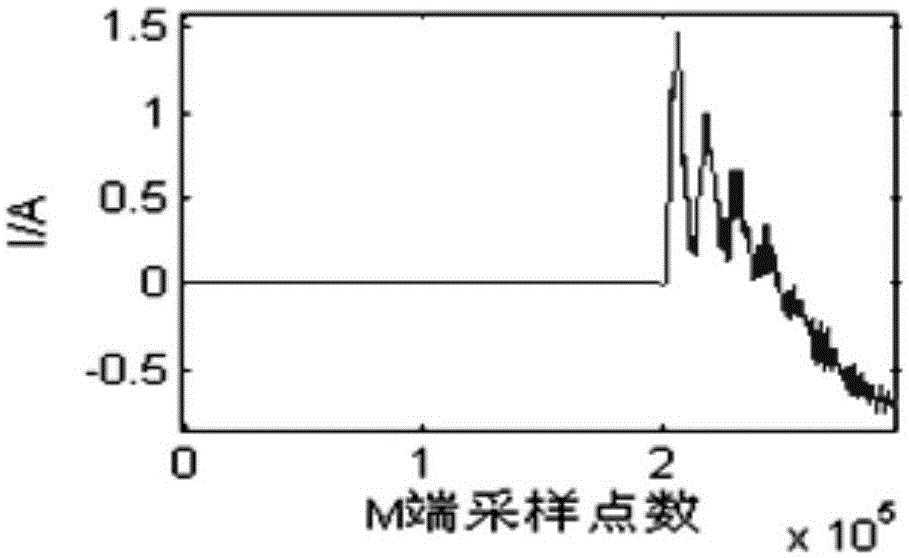
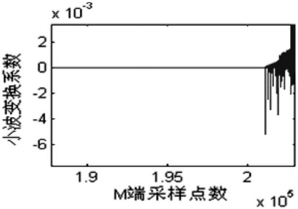
The invention discloses a positioning method of fault points in power distribution network mixed circuits. The positioning method comprises steps of adopting the method of monitoring external faults and measuring propagation speed of fault traveling waves in a cable circuit in an on-line manner; supposing one end in any one circuit zone breaks down and calculating time difference that the initial fault traveling waves achieve two measuring ends of the mixed circuit; setting the time difference as the node time difference, establishing corresponding relations between ends in circuit zone and the node time difference and storing the corresponding relations into a data base; when the mixed circuit breaks down, measuring the actual measurement time difference that the initial fault travelling waves reach two measuring ends of the mixed circuit; comparing the actual measurement time difference with the node time difference in the data base and determining fault circuit zones; and calculating the position of the actual fault point according to the factor that the difference value between the actual measurement time difference and the corresponding node time difference of the end in the fault circuit zone multiplied by a half of the propagation speed value of the fault travelling waves in the fault circuit zone equals the distance between the fault point and the fault circuit zone.
Description
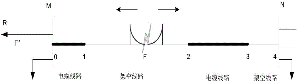
technical field The invention belongs to the field of electric power, in particular to a method for locating a fault point in a hybrid line of a distribution network. Background technique With the development of the power system, overhead-cable hybrid lines are more and more widely used in the power grid, especially in the distribution network. The structure of the distribution network is complex, there are many branches, and the fault current is small. It is difficult to use the electrical quantity to locate the fault. Quantity is important. At present, the traveling wave fault location technology has been successfully applied in the transmission network, and it will be an important research direction to study the traveling wave fault location technology in the distribution network. At present, some scholars at home and abroad have carried out research on hybrid line fault traveling wave location technology. The traditional methods include the simplification method, th...
Claims
Login to View More Application Information
Patent Timeline
 IPC IPC(8): G01R31/08
CPCH02H7/265
Inventor郑壮壮刘海客贾涛牟黎张艳杰任玉保张正茂
OwnerSTATE GRID OF CHINA TECH COLLEGE