A current control method suitable for high phase-locked loop bandwidth

A current control and phase-locked loop technology, which is applied to electrical components, output power conversion devices, AC power input to DC power output, etc., can solve the problems of complex modeling of phase-locked loop small signals, and avoid mutual resonance Effect

Active Publication Date: 2021-03-30
UNIV OF ELECTRONICS SCI & TECH OF CHINA
View PDF2 Cites 0 Cited by
  • Summary
  • Abstract
  • Description
  • Claims
  • Application Information

AI Technical Summary

Problems solved by technology

Phase detection in PLLs is implemented by the Park transform (dq), which is highly nonlinear and time-varying, making small-signal modeling of PLLs very complex

Method used


Image

  • A current control method suitable for high phase-locked loop bandwidth
  • A current control method suitable for high phase-locked loop bandwidth
  • A current control method suitable for high phase-locked loop bandwidth

Examples


Embodiment

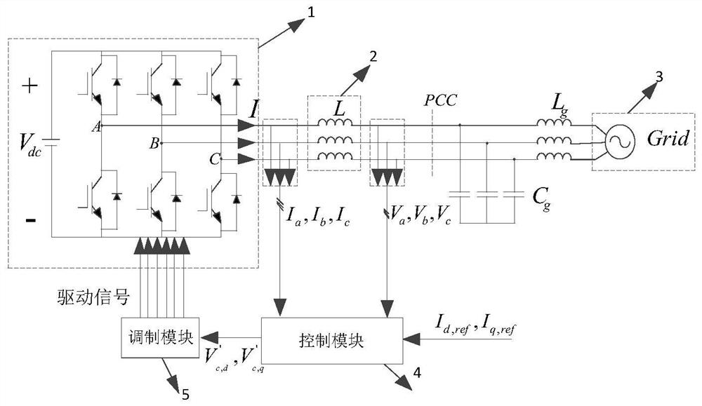
[0033] figure 1 It is a three-phase L-type grid-connected inverter main circuit and its control structure diagram.

[0034] In this example, if figure 1 As shown, the three-phase L-type grid-connected inverter includes a main circuit, a control module and a modulation module. The main circuit part is composed of inverter main circuit 1, L-shaped filter 2 and power grid 3. The inverter main circuit 1 is connected to the power grid 3 through an L-shaped filter 2, L g and C g Simulate grid impedance. The main circuit parameters are shown in Table 1:

[0035] Table 1 is the main circuit parameter table;

[0036] symbol name value V dc

DC side voltage 300V V g

Grid phase voltage peak value 110V I refd

d-axis reference current 5A I refq

q-axis reference current 0 f s

Control and Sampling Frequency 10KHz f sw

operating frequency 10KHz f c

Grid fundamental frequency 50Hz L filter inducto...


PUM


Abstract

The invention discloses a current control method suitable for a high phase-locked loop bandwidth. By separately considering the influence of the phase-locked loop on the modulation voltage, a suitable compensation coefficient K is selected, and the q-axis offset ΔV of the grid voltage is adjusted. q Make adjustments to counteract the influence of the phase-locked loop on the modulation voltage, thereby avoiding the mutual resonance between the power grid and the inverter due to the increase in the bandwidth of the phase-locked loop, so that when the bandwidth of the phase-locked loop reaches several hundred Hz, the dq coordinate system The current inner loop control can still maintain stability, thereby improving the robustness of the inverter to changes in the bandwidth of the phase-locked loop.

Description

technical field [0001] The invention belongs to the technical field of three-phase grid-connected inverters, and more specifically relates to a current control method suitable for high phase-locked loop bandwidth. Background technique [0002] With the increase of renewable power (wind power, photovoltaic) grid-connected power level and wide distribution location, the scale and distance of power transmission continue to grow, and the power grid gradually shows insufficient anti-disturbance capability. In recent years, the problem of mutual resonance between renewable energy converters and power grids has emerged in China, the United States and Europe. The stability of a system containing multiple grid-connected inverters is often difficult to analyze, especially when the inverters have different voltage levels and dynamic characteristics. [0003] In order to solve the stability challenge caused by the mutual resonance between the converter and the grid, the stability analy...

Claims


Application Information

Patent Timeline
Patent Type & Authority Patents(China)
IPC IPC(8): H02J3/38H02M7/5387
CPCH02J3/38H02M7/5387
Inventor 李凯彭颖郑宏谢川邹见效徐红兵
Owner UNIV OF ELECTRONICS SCI & TECH OF CHINA
Why Eureka
Try Eureka