
Camera assembly and terminal

A camera assembly and camera technology, applied in electrical components, image communication, color TV components and other directions, can solve the problems of inconvenient use, fixed camera angles, and difficulty in multi-directional framing, etc., to improve shooting performance and flexible shooting. Effect

Pending Publication Date: 2018-09-28
SHANGHAI IUV SOFTWARE DEV CO LTD
View PDF0 Cites 1 Cited by
  • Summary
  • Abstract
  • Description
  • Claims
  • Application Information

AI Technical Summary

Problems solved by technology

[0002] In the field of mobile terminals, the size requirements of the camera are very strict. If the size is too large, it will seriously affect the shape of the mobile terminal; the installation form of the camera is perpendicular to the display screen of the mobile terminal, and the length of the camera is limited by the thickness of the mobile terminal. Can not be too large, this structural limitation will affect the camera's camera performance
In the prior art, there are some external devices (expansion lens) to enhance the function of the camera, but each time it needs to be connected and operated, which has the disadvantage of being inconvenient to use
[0003] In addition, most of the cameras used in mobile terminals in the prior art are non-adjustable fixed structures, with fixed camera angles and a single shooting angle, making it difficult to view from multiple directions

Method used


Image

  • Camera assembly and terminal
  • Camera assembly and terminal
  • Camera assembly and terminal

Examples


Embodiment Construction

[0024] The following description with reference to the accompanying drawings is intended to facilitate a comprehensive understanding of various embodiments of the present application as defined by the claims and their equivalents. These examples include various specific details to facilitate understanding, but these are to be regarded as exemplary only. Accordingly, those of ordinary skill in the art will understand that various changes and modifications of the various embodiments described herein can be made without departing from the scope and spirit of the application. Also, the present application will omit descriptions of well-known functions and constructions in order to briefly and clearly describe the present application.

[0025] The terms and phrases used in the following description and claims are not limited to the bibliographical meanings, but merely to enable a clear and consistent understanding of the application. Accordingly, it will be understood by those ski...


PUM


Abstract

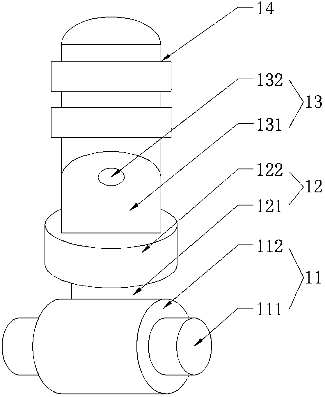
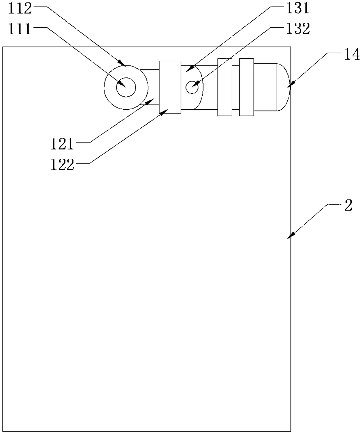
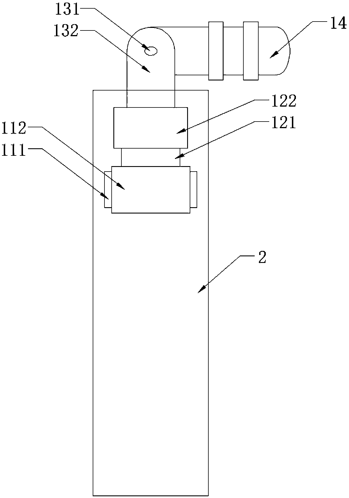
The invention discloses a camera assembly and a terminal and relates to the field of a terminal device. The camera assembly comprises a first rotation structure, a second rotation structure, a third rotation structure and a camera. One end of the first rotation structure is connected with the second rotation structure, the second rotation structure is enabled to rotate in a first plane, and the first plane is parallel to a display screen. The second rotation structure is connected with the third rotation structure, the third rotation structure is enabled to rotate in a second plane, and the second plane is vertical to the second rotation structure. The third rotation structure is connected with the camera, the camera is enabled to rotate in a third plane, and the third plane is parallel tothe third rotation structure. The camera is fixed through utilization of the first rotation structure, the second rotation structure and the third rotation structure, the camera is enabled to have three moving degree of freedom, a traditional camera mounting form can be changed, the camera is enabled to be parallel to the display, and the limitation to a size of the camera is reduced, so the photographing performance of the camera is improved.

Description

technical field [0001] The present application relates to the field of terminal equipment, in particular to a camera assembly and a terminal. Background technique [0002] In the field of mobile terminals, the size requirements of the camera are very strict. If the size is too large, it will seriously affect the shape of the mobile terminal; the installation form of the camera is perpendicular to the display screen of the mobile terminal, and the length of the camera is limited by the thickness of the mobile terminal. Can not be too large, this structural limitation will affect the camera performance. There are some external devices (extension lens) in the prior art to strengthen the function of the camera, but each use requires connection operation, which has the disadvantage of being inconvenient to use. [0003] In addition, most of the cameras used in mobile terminals in the prior art are non-adjustable fixed structures with fixed and single shooting angles, making it d...

Claims


Application Information

Patent Timeline
Patent Type & Authority Applications(China)
IPC IPC(8): H04N5/225
CPCH04N23/58H04N23/50H04N23/57
Inventor 蒋二吉蒋杰张志勇
Owner SHANGHAI IUV SOFTWARE DEV CO LTD
Learn More