Novel press gate adjustment device and adjustment method

A technology of an adjusting device and an adjusting method, which is applied in the manufacturing of laminated printed circuit boards, electrical components, printed circuits, etc., can solve problems such as deformation of the door of the press, and achieve the effects of reducing work intensity, simple alignment, and solving deformation.

Inactive Publication Date: 2018-09-28
SHENZHEN SUNTAK MULTILAYER PCB
View PDF4 Cites 0 Cited by
  • Summary
  • Abstract
  • Description
  • Claims
  • Application Information

AI Technical Summary

Problems solved by technology

[0007] The present invention aims at the problems of the above-mentioned defects in the prior art, and provides a novel press door adjustment device. With the adjustment device, the alignment between the press door and the screw holes of the machine body is simple, time-saving and labor-saving, and the work of the employees can be greatly reduced. It can also protect the door of the press, which solves the defect that the door of the press is easily deformed in the original method

Method used


Image

  • Novel press gate adjustment device and adjustment method
  • Novel press gate adjustment device and adjustment method
  • Novel press gate adjustment device and adjustment method

Examples


Embodiment 1

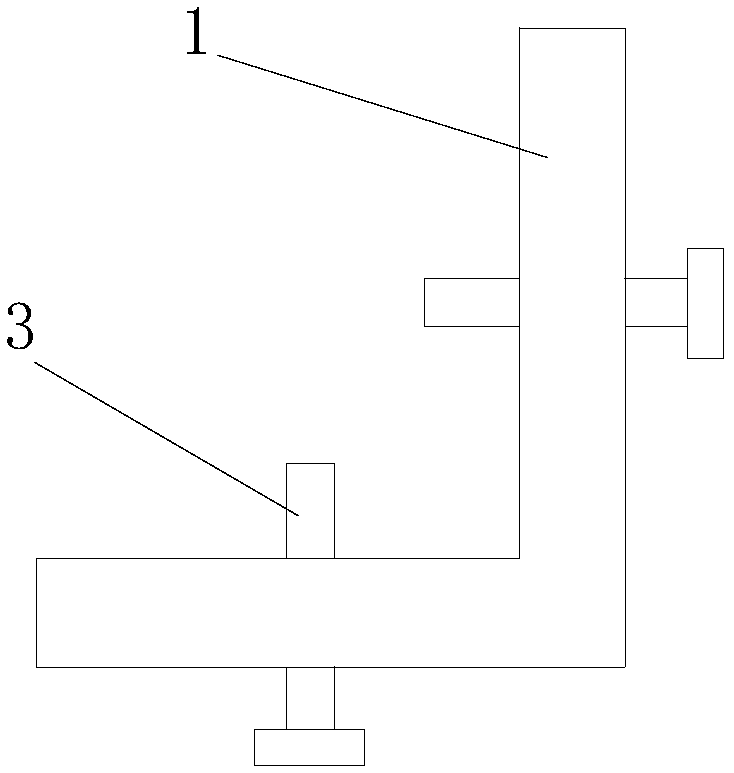
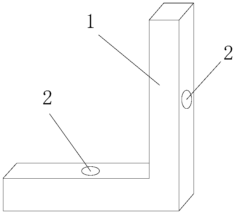
[0027] Such as figure 1 and figure 2 As shown, a novel press gate adjustment device shown in this embodiment includes an L-shaped frame 1, a threaded hole 2 is provided on both sides of the L-shaped frame 1, and matching bolts are set on the threaded hole 2. 3.

[0028] Specifically, the diameter of the threaded hole 2 is 10mm, and the bolt 3 is an M10 bolt with a length of 10cm.

[0029] Specifically, the thickness of the L-shaped frame 1 is greater than 1.5 cm to ensure the strength of the L-shaped frame.

[0030] Such as figure 2 As shown, in another embodiment of the present invention, the two sides of the L-shaped frame have the same length, and the distance between the threaded holes on the two sides and the intersection of the right angles on the L-shaped frame is the same; Relative position, the length of any side can be used as bottom or side.

[0031] Specifically, the threaded holes are respectively arranged in the middle of the two sides of the L-shaped fram...

Embodiment 2

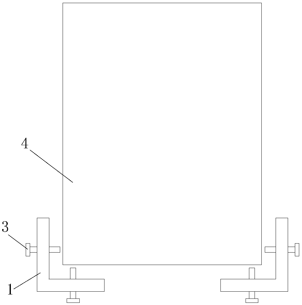
[0033] Such as image 3 As shown, there is also provided an adjustment method for adjusting the press gate using the novel press gate adjusting device of the above embodiment, including the following steps:

[0034] (1), two L-shaped frames 1 are respectively fixed on the outside of the two corners below the press door 4, and the two threaded holes on the L-shaped frame 1 correspond to the bottom and the side of the press door 4 respectively;

[0035] (2), install the matching bolt 3 on the threaded hole;

[0036] (3) Adjust the position of the press door 4 up, down, left, and right through the four bolts 3 on the two L-shaped frames 1, so that the screw holes on the press door and the press body are aligned;

[0037] (4) Install screws on the screw holes to fix the press door and the press body together.

[0038] Specifically, in step S1, the two L-shaped frames 1 are respectively fixed on the outside of the two corners below the press door and away from the press door by m...


PUM


Abstract

The invention discloses a novel press gate adjustment device and an adjustment method. The adjustment device comprises an L-shaped frame, wherein a threaded hole is formed in each of two edges of theL-shaped frame; and an assorted bolt is arranged on each threaded hole in a sleeving manner. By adoption of the adjustment device disclosed by the invention, a press gate is simply aligned with screwholes of a machine body, so that time and labor are saved; the working intensity of a worker can be substantially relieved; the press gate can be further protected; and the defect that the press gatedeforms easily in the original method is overcome.

Description

technical field [0001] The invention relates to the technical field of printed circuit board production, in particular to a novel press gate adjustment device and adjustment method. Background technique [0002] In the production process of printed circuit boards, some large presses are used to press the circuit boards; take the circuit board printing equipment-Boco press as an example, there is a heavy-duty sealing door on the press, because The door of the press is made of pure metal, with a weight of 300Kg and a large volume (2.5m in height, 1.5m in width, and 0.05m in thickness). The door is locked with the body of the press to achieve the purpose of tight sealing. [0003] However, the method of locking with screws will have the following defects: [0004] 1. Every time the door of the press is closed, the screw holes on the door and the screw holes on the machine body are difficult to align, so sometimes the screws cannot be fully tightened due to deviations in the a...

Claims


Application Information

Patent Timeline
Patent Type & Authority Applications(China)
IPC IPC(8): H05K3/00
CPCH05K3/0058
Inventor 闻平魏焕城李世明彭国东
Owner SHENZHEN SUNTAK MULTILAYER PCB
Why Eureka
Try Eureka