
Method for producing and assembling micro-channel heat exchanger

A micro-channel heat exchanger, production and assembly technology, applied in the direction of heat exchanger type, heat exchanger shell, indirect heat exchanger, etc., can solve the problem of oxidation black residue attached to the guard plate, deformation of the core guard plate, complex process and other issues, to achieve the effect of reducing material cost, improving production efficiency, and smooth and beautiful surface

Active Publication Date: 2013-10-02
浙江康盛热交换器有限公司
View PDF6 Cites 0 Cited by
  • Summary
  • Abstract
  • Description
  • Claims
  • Application Information

AI Technical Summary

Problems solved by technology

[0005] The purpose of the present invention is to solve the problems of existing micro-channel heat exchangers such as the use of stainless square tubes to reinforce the core before brazing, resulting in the deformation of the core guard plate, the adhesion of black oxidation residues to the guard plate, high cost and complicated process. A method for producing and assembling a microchannel heat exchanger, which optimizes the structure of the upper and lower guard plates, reduces production workload, and improves production efficiency

Method used


Image

  • Method for producing and assembling micro-channel heat exchanger
  • Method for producing and assembling micro-channel heat exchanger
  • Method for producing and assembling micro-channel heat exchanger

Examples


Embodiment Construction

[0015] The technical solutions of the present invention will be further specifically described below through the embodiments and in conjunction with the accompanying drawings.

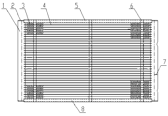
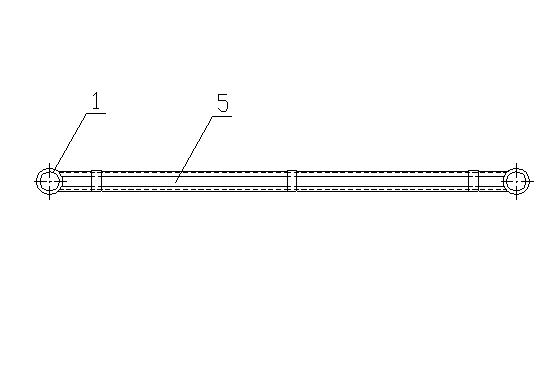
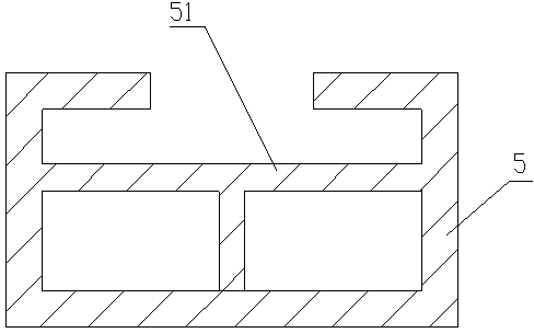
[0016] Such as figure 1 , figure 2 As shown, this embodiment is a production and assembly method of a microchannel heat exchanger, and the porous flat tubes 4 are evenly arranged between the headers 1 on both sides parallel to each other, and the porous flat tubes 4 are parallel to each other and perpendicular to the header 1 , All adjacent porous flat tubes 4 are provided with heat dissipation strips 3 . The ends of the collecting pipes 1 on both sides are blocked by end caps 2 , and the collecting pipe 1 is provided with a divider 7 for flow diversion. The inner side of the heat dissipation belt 3 located at the edge of the header 1 in the length direction is equipped with a porous flat tube 4, and the outer sides of the heat dissipation belt 3 are the upper guard plate 5 or the lower guard plate ...


PUM


Abstract

The invention relates to a micro-channel heat exchanger technology, in particular to a method for producing and assembling a micro-channel heat exchanger. According to the method, the problems of deformation of a core body protective plate and oxidized black residues attached to the protective plate caused by that the core body of the micro-channel heat exchanger is reinforced by a stainless steel square pipe before braze welding are solved. The method is characterized in that porous flat pipes are arranged between collecting pipes on two sides uniformly in parallel; a radiating belt is arranged between the adjacent porous flat pipes; the end parts of the parallel and symmetrical collecting pipes are plugged by end covers; partition boards are arranged in the collecting pipe; the porous flat pipes are arranged on the inner sides of the radiating belts on the edge of the length direction of the collecting pipes; upper protective plates or lower protective plates are arranged on the outer sides of the radiating belts; the protective plates and the lower protective plates are bundled by a plurality of steel belts; the core body, bundled by the steel belts, of the micro-channel heat exchanger is conveyed to a nitrogen protection high-temperature brazing furnace to be welded; and after the core body of the micro-channel heat exchanger moves out of the nitrogen protection high-temperature brazing furnace, the steel belts are removed. According to the method, no deformation defect exists, the surface is smooth, clean and attractive, and production efficiency is high.

Description

technical field [0001] The invention relates to a microchannel heat exchanger technology, in particular to a production and assembly method of a microchannel heat exchanger. Background technique [0002] The core of the microchannel heat exchanger is generally composed of a header, a porous flat tube, a heat dissipation belt, and upper and lower guard plates. A plurality of porous flat tubes are arranged between the symmetrical headers, and a heat dissipation belt with a louver structure is added in the middle of the porous flat tubes, and the heat dissipation belts on both sides of the edge are respectively protected by the porous flat tubes and the guard plate. The core body of the micro-channel heat exchanger assembled with the header, porous flat tube, heat dissipation belt, and upper and lower guard plates is pre-tightened and fixed with steel belts to prevent the parts from loosening and falling off each other, and the micro-channel after pre-tightening and fixing The...

Claims


Application Information

Patent Timeline
Patent Type & Authority Patents(China)
IPC IPC(8): F28D1/053F28F9/00
Inventor 闫志恒许显钧徐巧
Owner 浙江康盛热交换器有限公司
Learn More