Method for pulling out embedded bushing

The technology of a bushing and an upper sleeve is applied in the field of the electric pull-out hole containing the workpiece, which can solve the problems of deformation of the bushing and the workpiece, and achieve the effects of avoiding deformation or damage, good effect and convenient use.

Inactive Publication Date: 2020-07-03
CHENGDU AIRCRAFT INDUSTRY GROUP
View PDF9 Cites 5 Cited by
  • Summary
  • Abstract
  • Description
  • Claims
  • Application Information

AI Technical Summary

Problems solved by technology

To solve the defect of bushing and workpiece deformation during the extraction process of the bushing, especially the blind ho

Method used


Image

  • Method for pulling out embedded bushing
  • Method for pulling out embedded bushing
  • Method for pulling out embedded bushing

Examples


Embodiment Construction

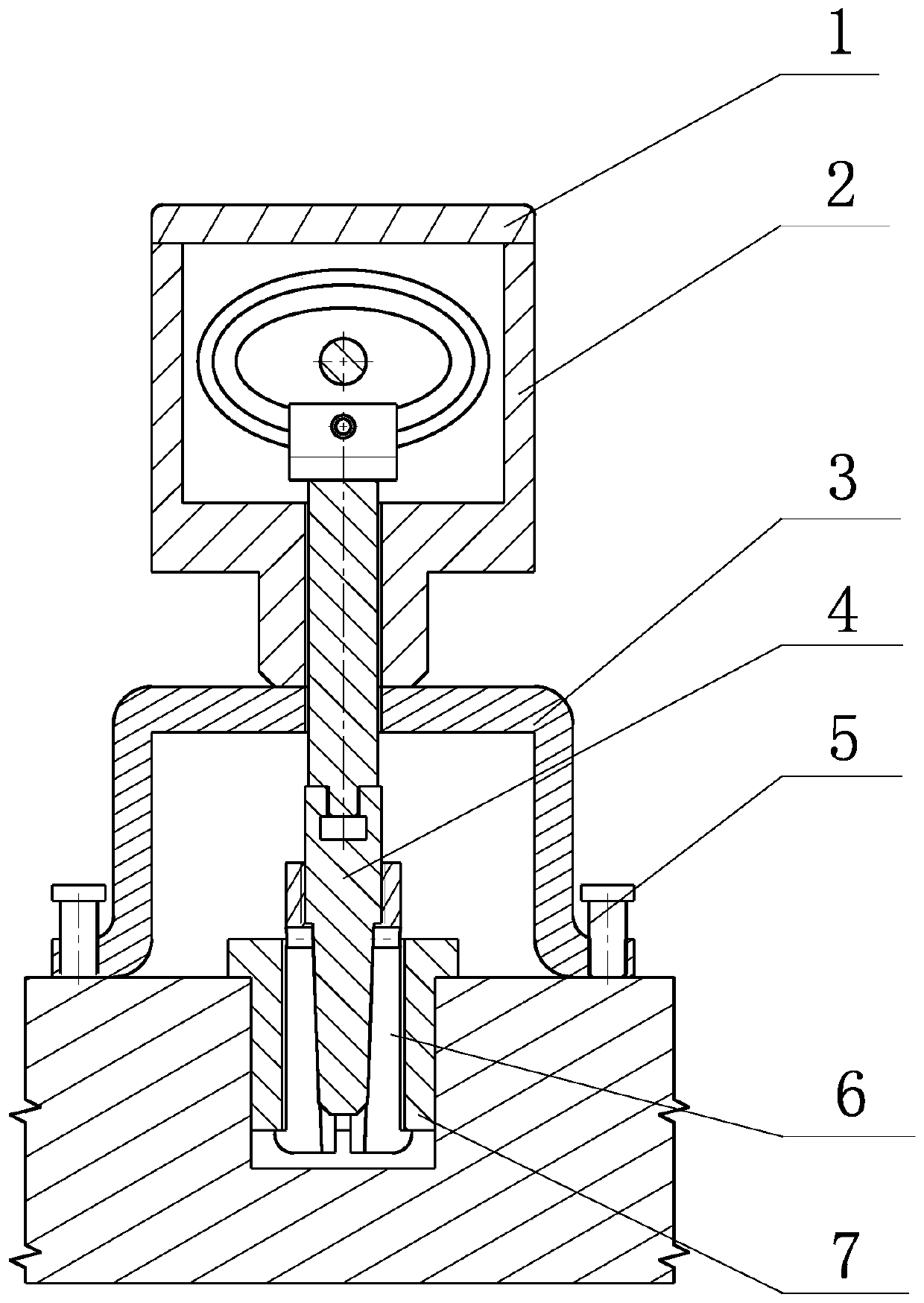
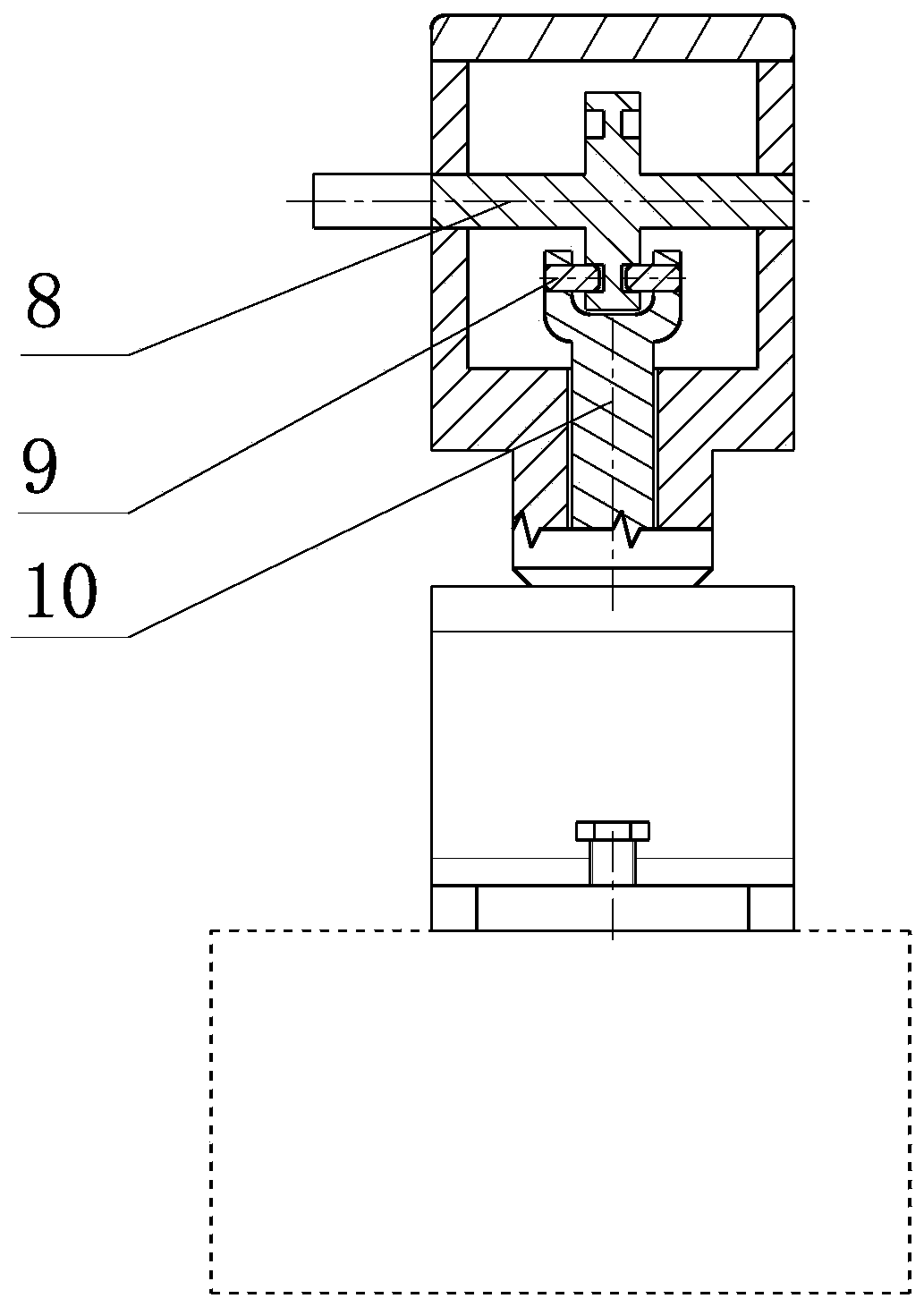
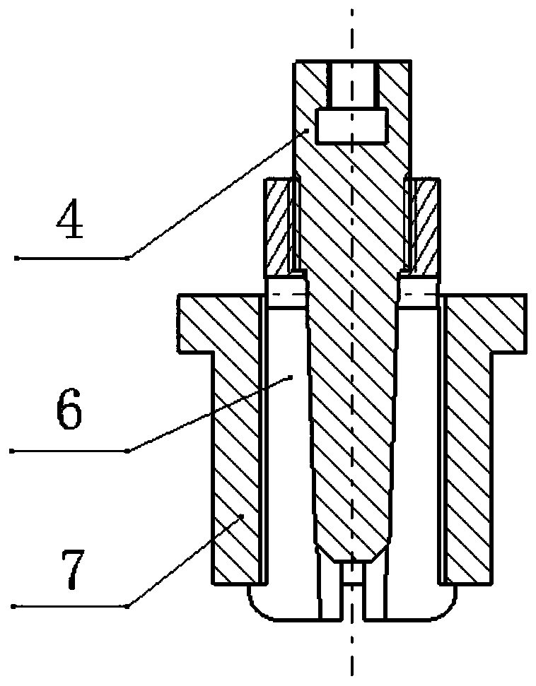
[0019] refer to Figure 1-Figure 5. According to the present invention, one prepares a pulling rod 10 that is inserted into the lower end step cylinder of the upper cover power cabin 2, the brim opening pressure seat 3 that can be fixed on the working surface of the workpiece bushing 7 and can be fixed along the inner wall of the workpiece bushing 7 It is inserted into the bottom end face of the workpiece hole, and is formed with an elastic expansion sleeve 6 with symmetrical opening grooves and end-bottom shackles, and a cam rotation shaft 8 assembled transversely through the cavity of the power cabin 2 of the upper cover. There is an opening groove connecting the short axis of the elliptical ring 11, and the other end is formed with a step buckle connecting the conical guide opening rod 4 gap groove; the elastic expansion sleeve 6 is radially contracted and inserted into the inner diameter of the workpiece bushing 7, and the rod 10 is pulled out Connect the conical guide op...


PUM


Abstract

The invention discloses a method for pulling out an embedded bushing, and aims to overcome the defect that the bushing is difficult to detach in the bushing pulling-out process. According to the technical scheme, the method comprises the following steps that a pull-up rod, a brim opening pressure bearing seat, an elastic expansion sleeve and a cam rotating shaft are prepared, wherein the pull-up rod is inserted into an upper sleeve power cabin, the brim opening pressure bearing seat is capable of being fixed to the working face of a workpiece bushing, the elastic expansion sleeve is capable ofbeing inserted into the bottom end face of a workpiece hole along the inner wall of the workpiece bushing and is provided with symmetrical opening grooves and end bottom hook rings, the cam rotatingshaft transversely penetrates through the cavity of the upper sleeve power cabin to be assembled; and the elastic expansion sleeve is inserted into the inner diameter of the workpiece bushing after being contracted in the radial direction. The pull-up rod is connected with a conical guide expansion rod, by utilizing the brim opening pressure bearing seat, an expansion pulling head of the conical guide expansion rod with a large upper part and a small lower part in taper falls into the elastic expansion sleeve inserted into the hole wall of the workpiece bushing through a supporting sleeve, thepull-up rod is driven by the cam rotating shaft, and a cam upwards and outwards pulls a pull head of the conical guide opening rod in a self-locking state with the inner wall of the elastic expansionsleeve through an elliptical ring, and the elastic expansion sleeve for fastening expansion of the inner hole wall of the workpiece bushing retreats the workpiece bushing inserted into the workpiecehole along with the elastic hook ring through an annular elastic hook ring clamped in the end direction and the expansion pulling head tightly pressing the inner wall of the bushing by virtue of axialcomponent force generated by the taper.

Description

technical field [0001] The invention relates to a method for containing a workpiece in an electric pull-out hole in the machinery manufacturing industry, in particular to a method for quickly pulling out various types of interference-fit bushes and drill sleeves and the old bush inlaid therein with auxiliary tools Extract method. Background technique [0002] The bushing is a thin-walled rotary workpiece with a simple structure, good centering with the hub hole, high load-bearing capacity and reliable operation under vibration, which is non-detachable or detachable. Vulnerable holes that need to be constantly replaced contain workpieces, occupy a large proportion in disassembly and assembly, and can be required not to destroy their matching properties and not to damage their working surfaces during disassembly and assembly of these parts. The more usual method when replacing after wear at present is to clamp the worn bushing on a lathe for turning. For the bushing embedded...

Claims


Application Information

Patent Timeline
IPC IPC(8): B25B27/02
CPCB25B27/02
Inventor 刘成向灿韩伟
Owner CHENGDU AIRCRAFT INDUSTRY GROUP
Why Eureka
Try Eureka