Brake system

a brake system and self-driving technology, applied in the direction of braking systems, positive displacement liquid engines, piston pumps, etc., can solve the problems of existing self-driving brake systems, damage or deformation of linkages or other structures, and vehicle accidents

Active Publication Date: 2020-09-29
ACER INC
View PDF19 Cites 1 Cited by
  • Summary
  • Abstract
  • Description
  • Claims
  • Application Information

AI Technical Summary

Benefits of technology

[0005]The disclosure provides a brake system, capable of improving the condition where the structure is damaged or deformed due to excessive rotation and reversal. When brake system is not automatically operated, the brake system can also be driven by an external force.
[0007]Based on the above, the brake system of the disclosure is adapted for self-driving vehicles, and the main control terminal of the self-driving vehicle controls the driving motor to rotate, and applies force to the braking pump through the cam, the bearing shaft and the rotating column for the self-driving vehicle to achieve deceleration. Since the disclosure employs a cam, when the driving motor is rotated excessively or reversely, the buffering effect of the cam can avoid damage or deformation of the bearing shaft or other components. In addition, the bearing shaft of the disclosure is only in alignment contact with the bearing shaft, and the two are still separate components. When the driving motor is not in operation, the user can still drive the rotating column separately through external force, and the force can be applied to the braking pump so as for the self-driving vehicle to achieve deceleration.

Problems solved by technology

However, the existing self-driving brake system is only controlled by its main control terminal.
When signal error is occurred to the main control terminal, the brake structure can be excessively rotated or reversed, resulting in damage or deformation of the linkage or other structure.
Or, the brake structure fails to work; as a result, the speed of the vehicle is not decelerated as expected, leading to vehicle accidents.

Method used


Image

  • Brake system
  • Brake system
  • Brake system

Examples


Embodiment Construction

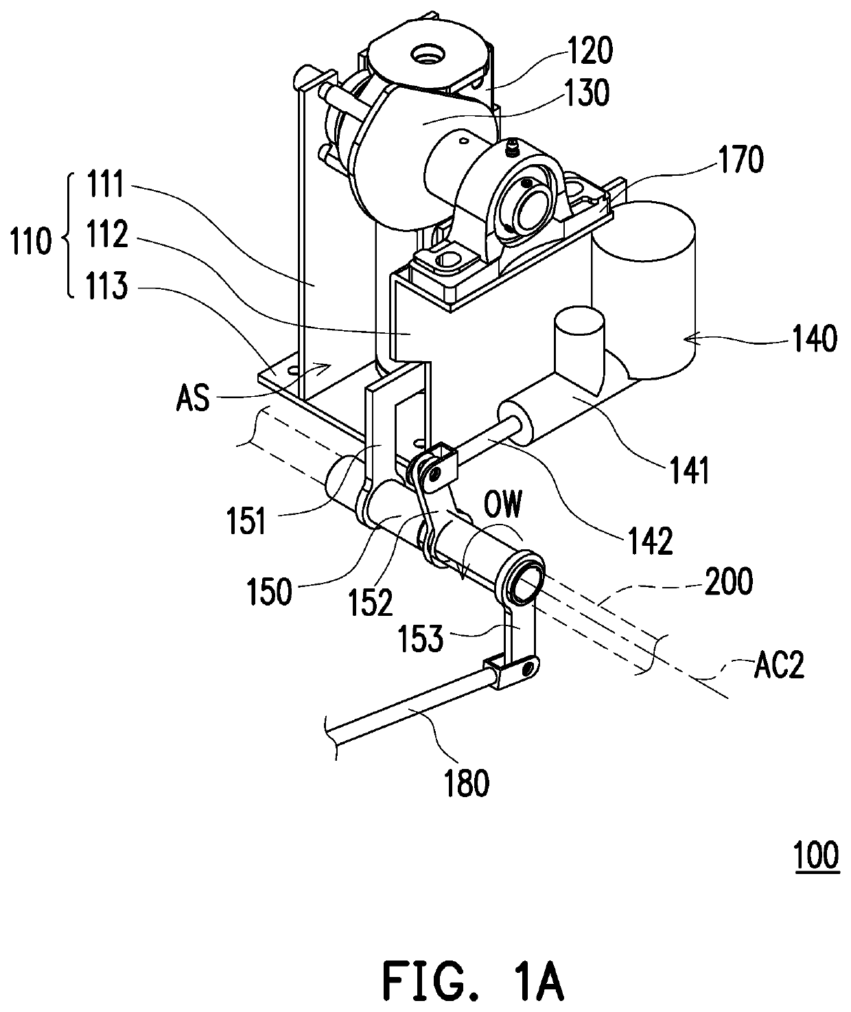
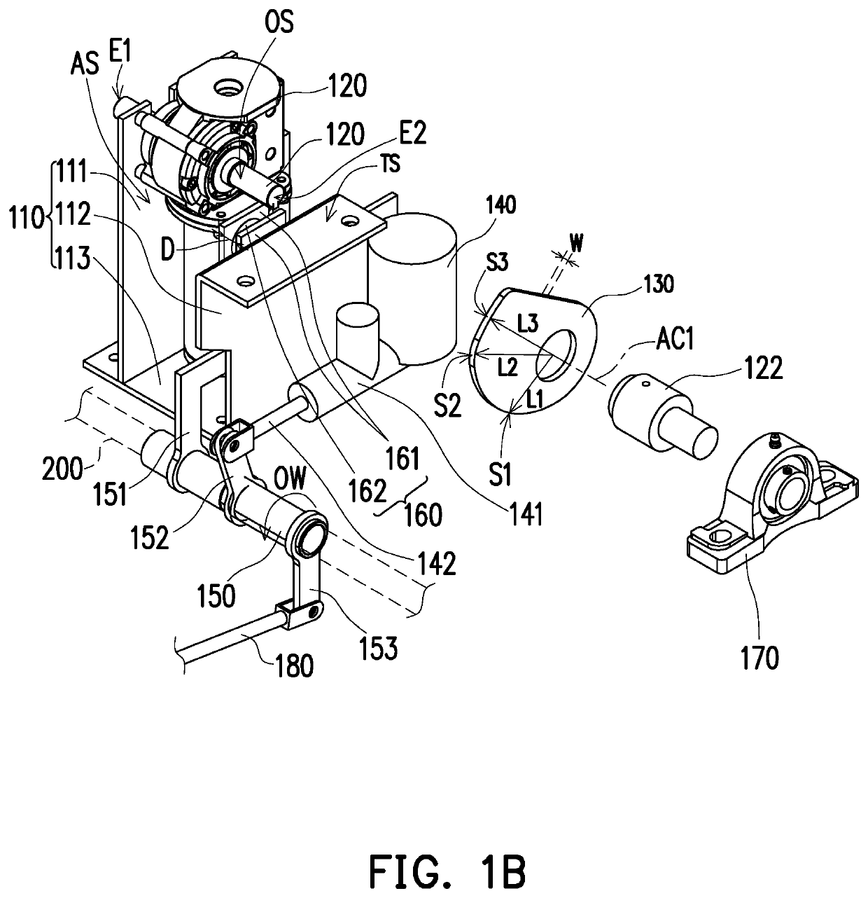
[0016]FIG. 1A is a schematic perspective view of a brake system according to an embodiment of the disclosure. FIG. 1B is a schematic perspective exploded view of some components of the brake system in FIG. 1A.

[0017]Referring to FIG. 1A and FIG. 1B, a brake system 100 of the disclosure is adapted for self-driving vehicles, and the brake system 100 is controlled by a control core of the self-driving vehicle. Briefly, the self-driving vehicle can make judgment on obstacles and road conditions in the environment through various sensors, and transmit the sensing signals to the control core. The control core determines whether to accelerate or decelerate the speed of the vehicle by logical calculation. When the control core determines that deceleration is required, the brake system 100 is activated to achieve automatic deceleration.

[0018]The brake system 100 of the exemplary embodiment includes a base 110, a driving motor 120, a cam 130, a braking pump 140, a rotating column 150, a bearin...


PUM


Abstract

A brake system including a base, a driving motor, a cam, a braking pump, a rotating column, and a bearing shaft. The base has an accommodating space. The driving motor is disposed on the base and located in the accommodating space. The cam is pivoted to the driving motor, and the driving motor is adapted to drive the cam to rotate relative to the base. The braking pump is disposed outside the base. The rotating column is rotatably disposed outside the base and connected to the braking pump. The bearing shaft is connected to the rotating column and extended into the accommodating space so as to radially in contact with the cam.

Description

CROSS-REFERENCE TO RELATED APPLICATION[0001]This application claims the priority benefit of Taiwan application serial no. 107133921, filed on Sep. 26, 2018. The entirety of the above-mentioned patent application is hereby incorporated by reference herein and made a part of this specification.BACKGROUND OF THE DISCLOSUREField of the Disclosure[0002]The disclosure relates to a brake system, and more particularly to a brake system that can be manually controlled when in a self-driving mode.Description of Related Art[0003]The existing vehicle brake system is roughly divided into two types: manual control brake and automatic control brake. The manual control brake is performed mainly by stepping on the brake plate to drive the brake structure to contact and rub against the tire to achieve deceleration. The automatic control brake is mainly applied to self-driving vehicles. The main control terminal of the self-driving vehicle makes judgment on obstacles and road conditions in the envirom...

Claims


Application Information

Patent Timeline
Patent Type & Authority Patents(United States)
IPC IPC(8): B60T13/20B60T7/12F04B17/03F04B9/04B60T17/02
CPCB60T13/20B60T17/02F04B17/03F04B9/042B60T7/12B60T7/22B60T2201/022B60T2210/20
Inventor WU, TSUNG-HSUNLEE, WEN-SHUCHANG, KUO-HUIWANG, CHIH-KAI
Owner ACER INC
Why Eureka
Try Eureka