Sliding connecting piece between steel member and concrete

A sliding connector and concrete technology, applied in the direction of building structure, construction, etc., can solve the problems of reducing the sliding capacity and working reliability of the connector, and achieve the effect of avoiding concrete cracking, avoiding damage and deformation, and low cost.

Inactive Publication Date: 2017-02-01
TIANJIN UNIV
View PDF8 Cites 0 Cited by
  • Summary
  • Abstract
  • Description
  • Claims
  • Application Information

AI Technical Summary

Problems solved by technology

There is also a kind of anti-pull and non-shear connector, because the way of arranging foam plastics on the sliding stroke is used to slide through the compression deformation of foam plastics. The latera

Method used


Image

  • Sliding connecting piece between steel member and concrete
  • Sliding connecting piece between steel member and concrete
  • Sliding connecting piece between steel member and concrete

Examples


Embodiment Construction

[0018] The present invention will be further described below in conjunction with the accompanying drawings.

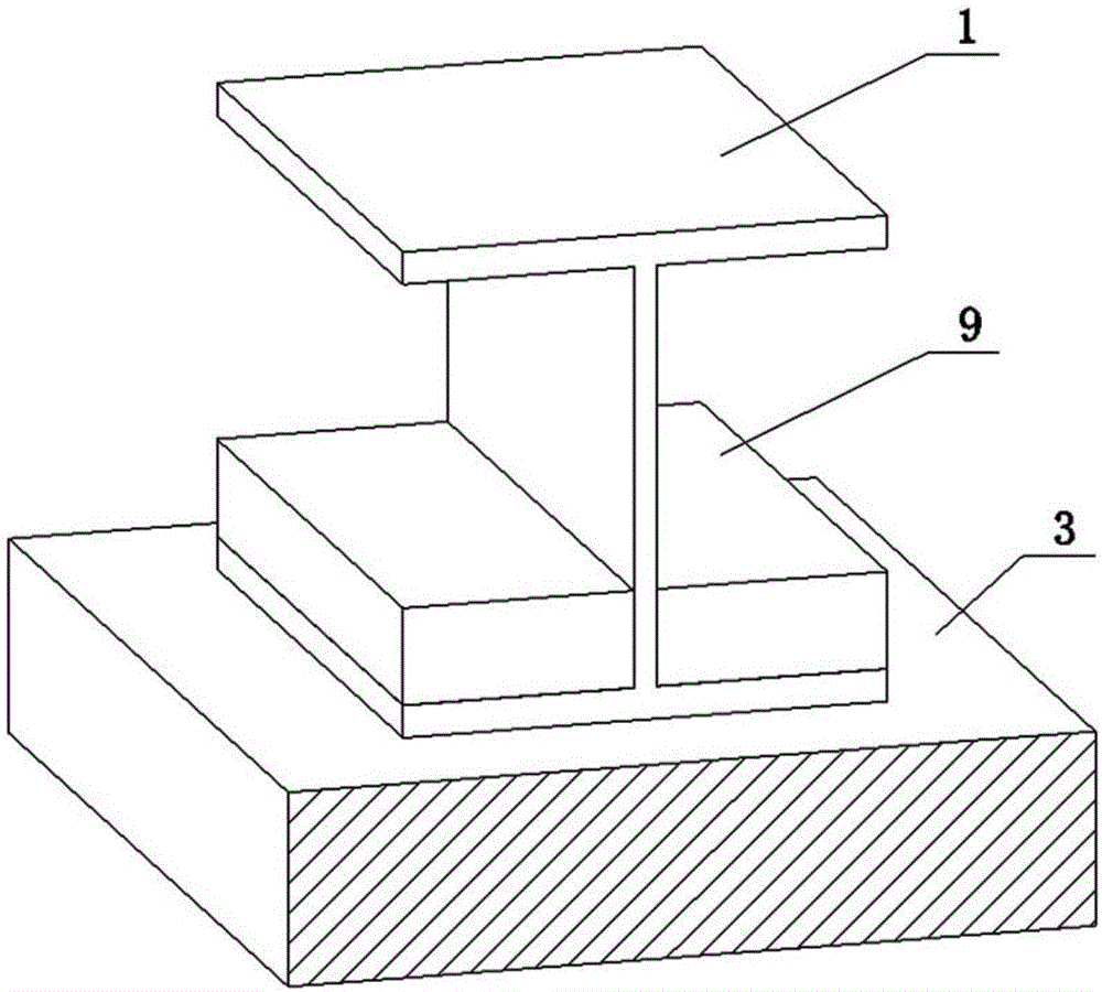
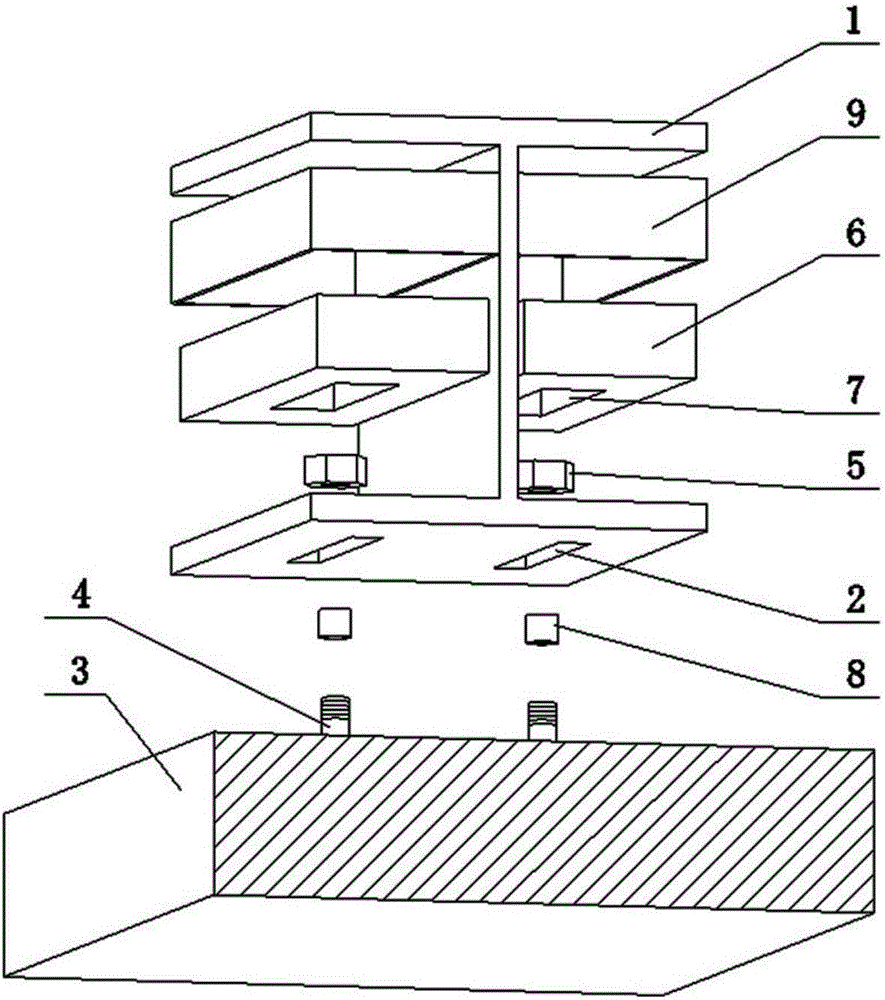
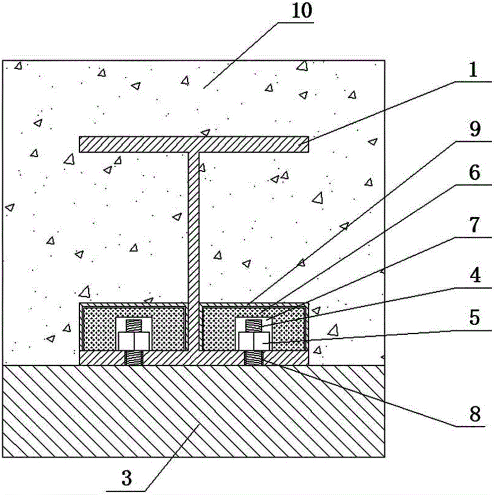
[0019] as attached figure 1 and figure 2 As shown, a sliding connection between a steel member and concrete includes an anchor 1 fixed in a concrete body 10, and at least one strip-shaped hole 2 is provided on the base of the anchor 1. In this embodiment, The anchor 1 is an I-shaped structure, and one strip-shaped hole 2 is provided on both sides of its base. Each of the strip-shaped holes 2 is provided with a bolt 4 fixed on the steel member 3 by welding or other means and a nut 5 matched with the bolt 4, and each of the bolts 4 is provided with a nut limit sleeve 8. Avoid the problem of losing the sliding connection function due to the nut 5 being pressed too tightly on the base of the anchor 1. At the same time, the nut 5 can be tightened on the nut limit sleeve 8 to avoid the separation of the steel member 3 and the concrete due to the loosening of the nut 5 qu...


PUM


Abstract

The invention discloses a sliding connecting piece between a steel member and concrete. The sliding connecting piece is composed of a connecting piece body, wherein the connecting piece body comprise an anchoring part fixed in a concrete body, at least one strip-shaped hole is formed in a base of the anchoring part, a bolt fixed to the steel member and a nut matched with the bolt are arranged in each strip-shaped hole, each strip-shaped hole is provided with a protective cover, and a cavity corresponding to the strip-shaped holes and containing the nuts and the bolts is formed in the lower portion of the protective cover. The sliding connecting piece permits that certain relative sliding between the steel member and the concrete under the condition that relative separation does not occur between the steel member and the concrete, and the problem of concrete cracking caused by the fact that a concrete member is pulled is avoided.

Description

technical field [0001] The invention relates to construction engineering, in particular to a sliding connection between steel components and concrete. Background technique [0002] In the composite structure, the connection between the steel member and the concrete is generally connected by studs, and the existing connectors ensure the joint work by limiting the relative slippage between the steel member and the concrete. However, for some parts or certain areas, it is necessary for the steel member and the concrete member to slide in one direction under the premise that they cannot be separated. For example, steel-concrete continuous composite beams or continuous composite slabs, the bending moment near the intermediate support is mainly negative bending moment, and the existing connectors will limit the relative slip between steel members and concrete in the negative bending moment area. Tensile stress is generated inside, and even the concrete cracks. Therefore, under t...

Claims


Application Information

Patent Timeline
IPC IPC(8): E04B1/41
CPCE04B1/41
Inventor 丁阳戴骁蒙宗亮严加宝薛磊
Owner TIANJIN UNIV
Why Eureka
Try Eureka