

Feeding cylinder structure of photoresist to photoetching machine
A photoresist and feeding barrel technology, which is applied in the field of photolithography machines, can solve the problems of plastic barrel deformation, rubber barrel leakage, and high air pressure, and achieve the effect of avoiding deformation or damage.
- Summary
- Abstract
- Description
- Claims
- Application Information
AI Technical Summary
Problems solved by technology
Method used
Image

Examples
Embodiment Construction
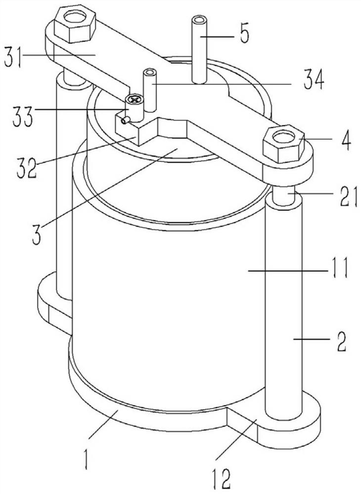
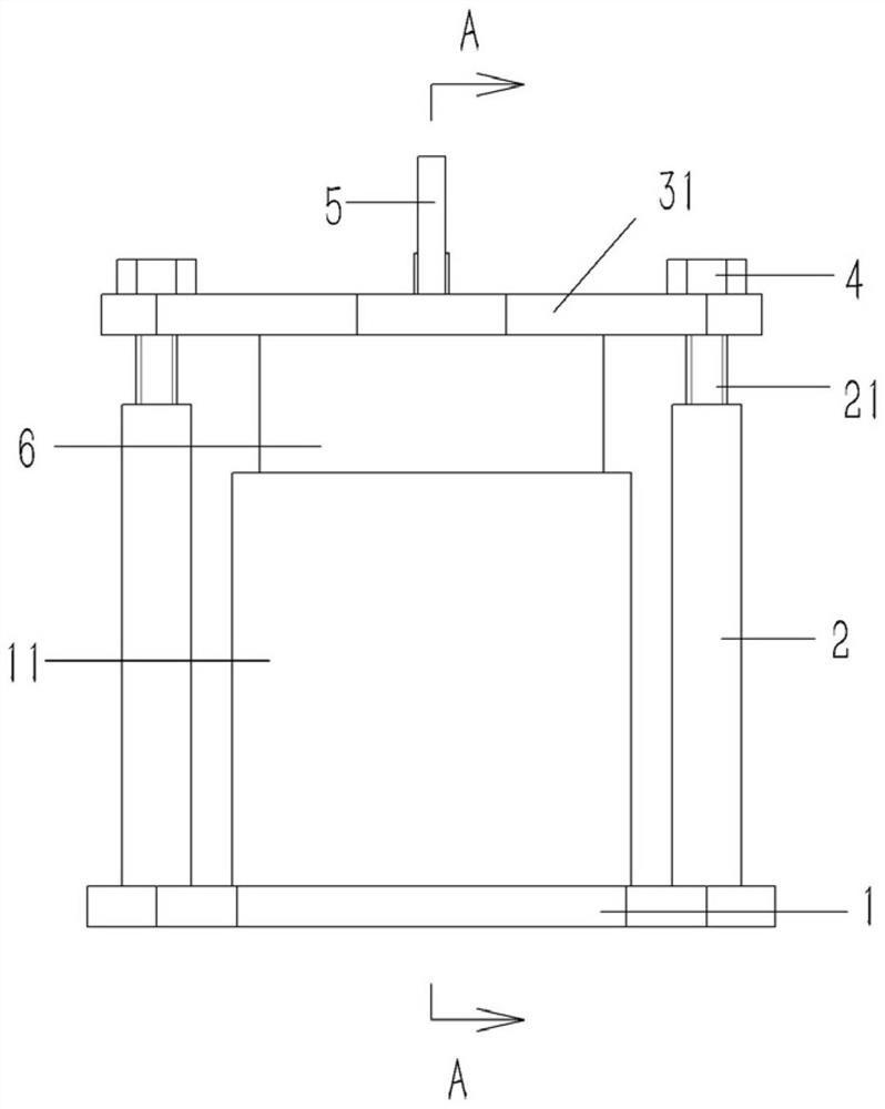
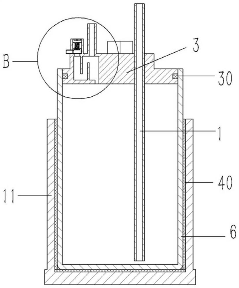
[0019] Example: see Figures 1 to 4 As shown, a photoresist material supply cylinder structure on a photolithography machine includes a tray 1, on which a rubber container 6 is placed, and lugs 12 are formed on opposite sides of the tray 1, and vertical lugs are fixed on the lugs 12. Straight connecting column 2, a vertical stud 21 is formed on the upper end surface of the connecting column 2, an annular protective cover 11 is formed on the upper end surface of the tray 1, and the plastic container 6 is inserted in the protective cover 11; The upper end of the plastic container 6 is plugged with a sealing cover 3, and the upper end surface of the sealing cover 3 is formed with a locking plate 31, and the two ends of the locking plate 31 protrude from the rubber container 6 to be inserted and sleeved on the stud 21, and the stud 21 A nut 4 is screwed on the top, and the nut 4 is pressed against the lock plate 31; the sealing cover 3 is plugged and fixed with a delivery tube 5, ...
PUM
 Abstract
Description
Claims
Application Information