Medical needle withdrawal assembly

A technology of needle assemblies and needle parts, which can be applied to needles and instruments introduced into the body, etc., can solve the problems of redness, swelling, a lot of outflow, and poor medical experience for patients.

Active Publication Date: 2018-10-02
鲍天琪
View PDF6 Cites 7 Cited by
  • Summary
  • Abstract
  • Description
  • Claims
  • Application Information

AI Technical Summary

Problems solved by technology

[0003] Due to the long time of the whole drip, it is impossible for the medical staff to monitor whether the patient's drip has been dripped at any time, and when the liquid in the infusion bottle is about to be dripped, if the patient cannot find the medical staff, there is no one around. If the patient chooses to pull out the needle by himself at this time, he can only pull it out with the other hand that is not connected to the IV. Set up a band-aid, but since the needle is still under the band-aid when the drip is hung, the patient must go through the following process when pulling out the needle by himself: the needle is pulled out from the patient's hand, and the gap between the band-aid and the needle pricking port flows out Blood, the patient puts down the needle, and then presses the bandage with his hand, a lot of blood will flow out during this process
[0004] After pulling out the injection needle, the patient usually uses the other hand that is not connected to the drip to press the needle pricking port. If the struggling port is kneaded during this process, redness and swelling will appear near the needle pricking port. The patient’s medical experience poor sense

Method used


Image

  • Medical needle withdrawal assembly
  • Medical needle withdrawal assembly

Examples


Embodiment Construction

[0020] The following is attached figure 1 - attached figure 2 The present invention is described in further detail.

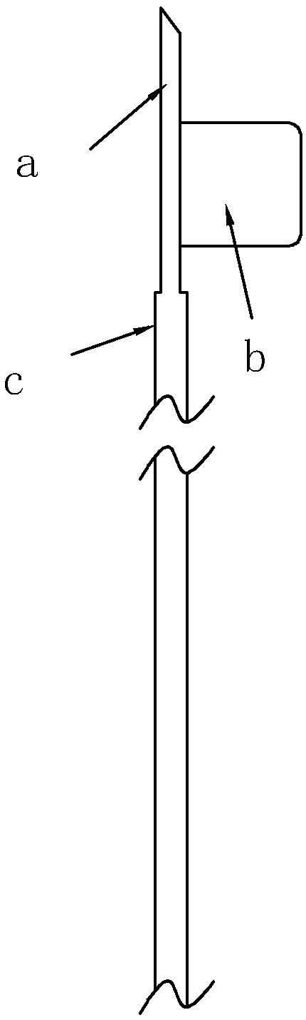
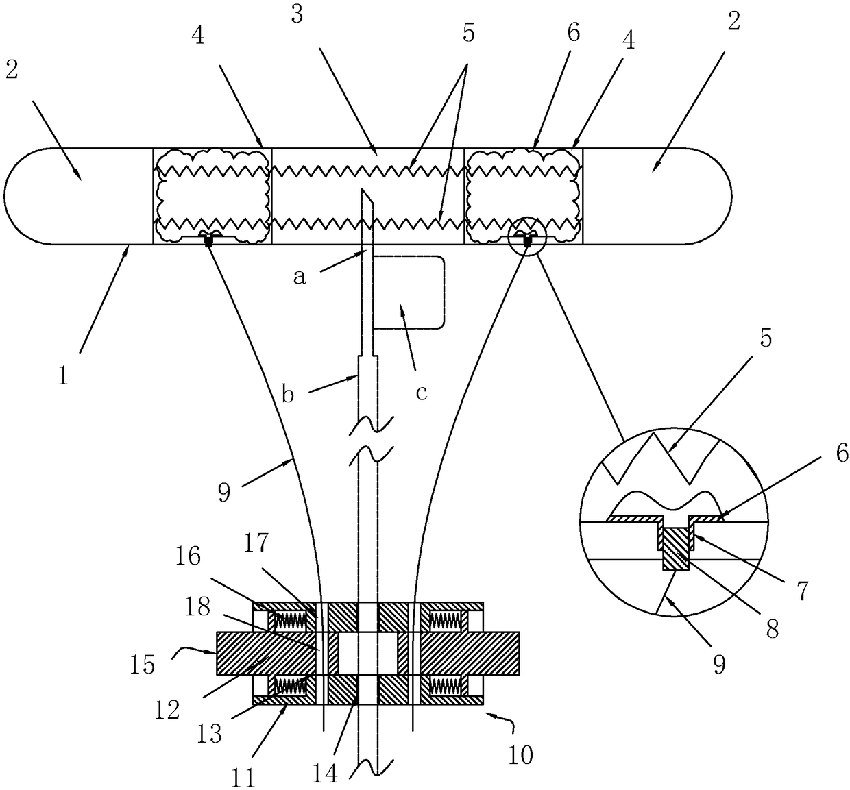
[0021] A medical needle pulling assembly, comprising a strip-shaped elastic wound band 1, the area near the two ends of the elastic wound band 1 is an adhesive area 2, and an adhesive layer is arranged in the adhesive area 2, and the adhesive layer can be connected with the patient Removable bonding occurs on the back of the hand; in the middle of the elastic wound band 1 is a gauze area 3 opposite to the wound, and the gauze area 3 is sterilized; a driving area 4 is respectively arranged on both sides of the gauze area 3, and each Each driving zone 4 is located between the bonding zone and the gauze zone 3.

[0022] All be provided with an air bag 6 in each driving area 4, the air bag 6 and the driving area 4 are all symmetrically distributed with the gauze area 3 as the center, the air bag 6 is provided with an air nozzle 7, and an air plug 8 is plugged in...


PUM


Abstract

The invention discloses a medical needle withdrawal assembly. The technical scheme mainly includes that the medical needle withdrawal assembly comprises an elongated elastic trauma band; regions whichare close to two ends of the elastic trauma band are adhesion regions, adhesive layers are arranged in the adhesion regions, a gauze region which is opposite to wound is arranged in the middle of theelastic trauma band, driving regions are arranged between the adhesion regions and the gauze region, contraction strips are arranged in the elastic trauma band and are butted to the two adhesion regions in a crossing manner, gas bags are arranged in the driving regions, gas nozzles are arranged on the gas bags, gas plugs are plugged in the gas nozzles, and connecting lines are connected onto thegas plugs; the medical needle withdrawal assembly further comprises a needle withdrawal component, the needle withdrawal component comprises a shell, a clamping portion for clamping an injection tubeis arranged in the shell, and an end of each connecting line is connected with the shell. The medical needle withdrawal assembly has the advantages that needle withdrawal and adhesive bandage stickingcan be synchronously carried out by the aid of the medical needle withdrawal assembly, and accordingly the medical needle withdrawal assembly is beneficial to enhancing the medical treatment experience feeling of patients.

Description

technical field [0001] The invention relates to medical supplies, in particular to a medical needle pulling assembly. Background technique [0002] In the process of medical rescue, it usually involves hanging drips, common drip injection heads, see the attached figure 1 , the structure includes a needle a, the needle a is provided with a clamping piece b, and the end of the needle a is butted with the injection tube c. [0003] Due to the long time of the whole drip, it is impossible for the medical staff to monitor whether the patient's drip has been dripped at any time, and when the liquid in the infusion bottle is about to be dripped, if the patient cannot find the medical staff, there is no one around. If the patient chooses to pull out the needle by himself at this time, he can only pull it out with the other hand that is not connected to the IV. Set up a band-aid, but since the needle is still under the band-aid when the drip is hung, the patient must go through the...

Claims


Application Information

Patent Timeline
Patent Type & Authority Applications(China)
IPC IPC(8): A61M5/158
CPCA61M5/158
Inventor 鲍天琪
Owner 鲍天琪
Why Eureka
Try Eureka