Automatic needle withdrawal assembly

A needle assembly and automatic technology, applied in the direction of needles and instruments introduced into the body, can solve problems such as redness, swelling, excessive outflow, and poor medical experience for patients

Active Publication Date: 2018-11-06
鲍雪花
View PDF7 Cites 6 Cited by
  • Summary
  • Abstract
  • Description
  • Claims
  • Application Information

AI Technical Summary

Problems solved by technology

[0003] Due to the long time of the whole drip, it is impossible for the medical staff to monitor whether the patient's drip has been dripped at any time, and when the liquid in the infusion bottle is about to be dripped, if the patient cannot find the medical staff, there is no one around. If the patient chooses to pull out the needle by himself at this time, he can only pull it out with the other hand that is not connected to the IV. Set up a band-aid, but since the needle is still under the band-aid when the drip is hung, the patient must go through the following process when pulling ...

Method used


Image

  • Automatic needle withdrawal assembly
  • Automatic needle withdrawal assembly
  • Automatic needle withdrawal assembly

Examples


Embodiment Construction

[0030] The following is attached Figure 1-5 The present invention will be described in further detail.

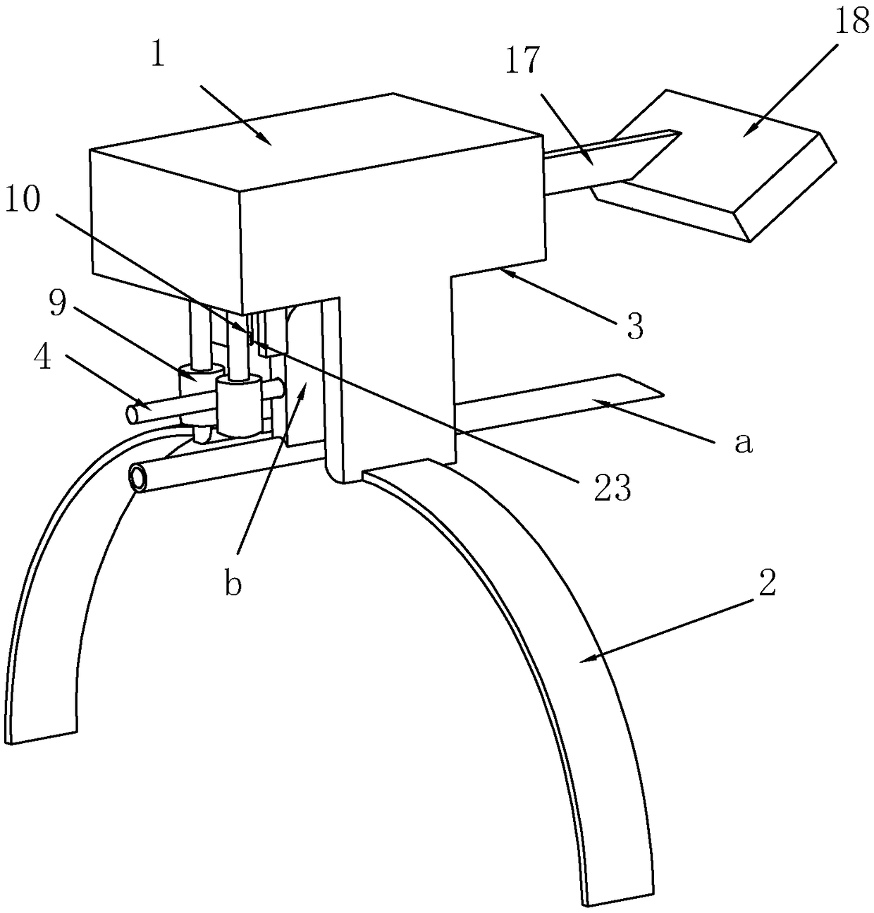
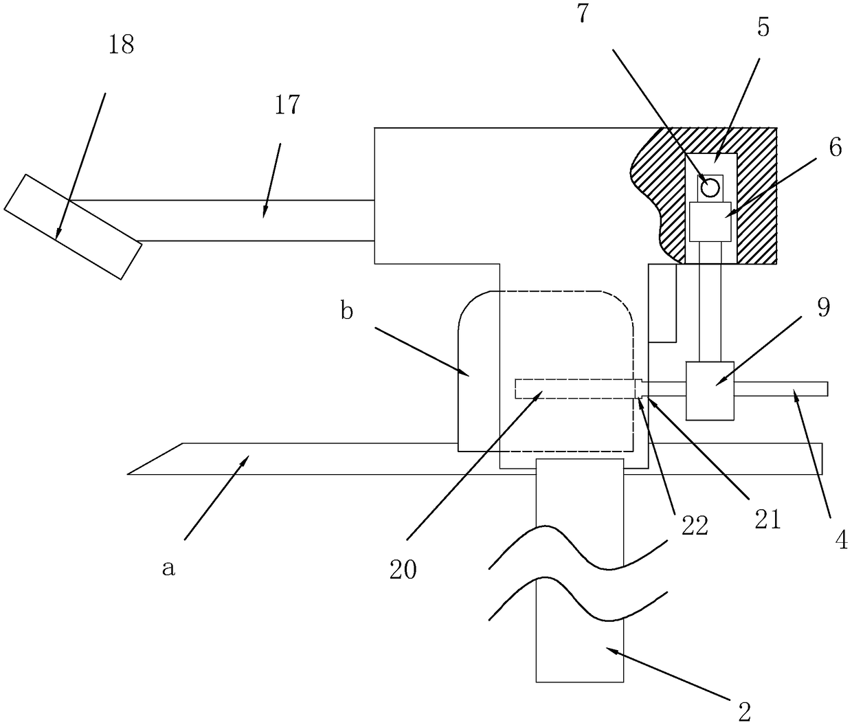
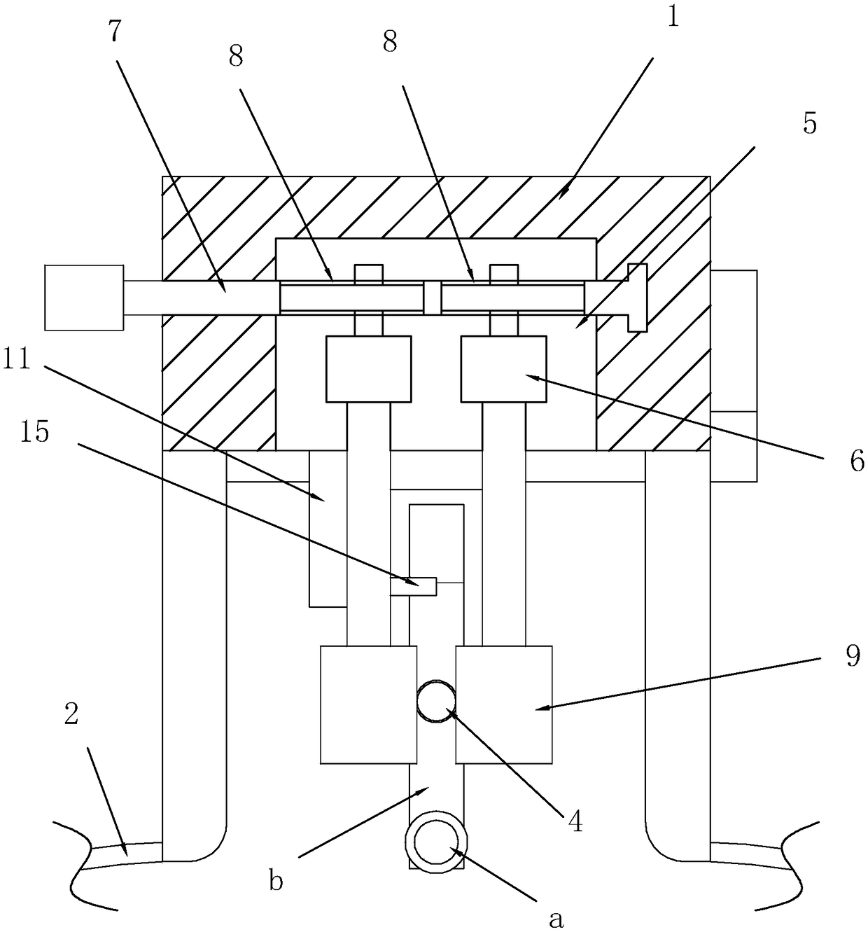
[0031] An automatic needle extraction assembly includes a traditional drip injection head. The drip injection head includes a needle a, a clamping piece b is provided on the needle a, and a sliding hole 20 is provided on the clamping piece b. The direction of the orifice is opposite to the direction of the tip of the needle a. A clamping rod 4 is provided in the sliding hole 20. A first positioning ring 21 is provided at the orifice of the sliding hole 20. The end of the clamping rod 4 is provided with a first positioning ring 21. Two positioning rings 22, the first positioning ring 21 and the second positioning ring 22 abut to restrict the clamping rod 4 from continuing to slide out of the sliding hole 20.

[0032] It also includes a main frame 1, on which a binding strap 2 is connected, and one side of the main frame 1 is a needle removal surface 3. When the binding strap 2 ...


PUM


Abstract

The invention discloses an automatic needle withdrawal assembly. According to the technical scheme, the assembly is characterized by comprising a syringe needle, wherein a clamping piece is arranged on the syringe needle. The assembly comprises a main frame body which is connected with a binding belt, one side of the main frame body is a needle withdrawal surface, and the binding belt is used forbinding the wrist; a clamping rod is arranged on the clamping piece, a sliding groove is formed in the needle withdrawal surface, and two driving motors are arranged in the sliding groove; a driving rod is arranged on the main frame body, two threaded sections are arranged on the driving rod, and the rotating directions of the two threaded sections are opposite; the driving rod penetrates throughthe sliding groove, and the threaded sections are located in the sliding groove; the two threaded sections are in threaded connection with the two driving motors respectively, and a motor shaft of each driving motor is provided with a clamping wheel; a battery and a control switch are arranged in the main frame body; a triggering part is arranged on the pin withdrawal surface, a rotating groove isformed in the main frame body, and a rotating arm is hinged to the interior of the rotating groove; a containing part is arranged at the end of the rotating arm, and a spring is arranged in the rotating groove. By means of the assembly, needle withdrawal and band-aid sticking can be completed at the same time, and the medical experience of a patient is improved.

Description

Technical field [0001] The invention relates to medical needle extraction equipment, in particular to an automatic needle extraction assembly. Background technique [0002] In the process of medical rescue, it usually involves hanging IV, common drip injection head, such as Image 6 As shown, the structure includes a needle a, and a clamping piece b is provided on the needle. [0003] Because the entire infusion takes a long time, and it is impossible for the medical staff to monitor whether the patient’s infusion has been completed at any time, and when the liquid in the infusion bottle is almost finished, if the patient cannot find the medical staff, there is no Accompanied by family members, the patient's mood at this time will be very irritable. At this time, if the patient chooses to remove the needle by himself, he can only use the other hand that does not hang the IV. Although the current position of the needle will be Set up a wound dressing, but because the needle is still...

Claims


Application Information

Patent Timeline
IPC IPC(8): A61M5/158
CPCA61M5/158A61M2005/1583
Inventor 鲍雪花
Owner 鲍雪花
Why Eureka
Try Eureka