
Liftable single-track bridge erecting machine

A bridge erecting machine, single track technology, applied in the direction of erecting/assembling bridges, bridges, bridge construction, etc., can solve the problems of many restrictions, unchanged use, large equipment limitations, etc., to ensure normal use and ensure safe use. , to ensure a stable effect

Active Publication Date: 2018-10-02
ZHEJIANG ZHONGJIAN ROAD & BRIDGE EQUIP
View PDF4 Cites 1 Cited by
  • Summary
  • Abstract
  • Description
  • Claims
  • Application Information

AI Technical Summary

Problems solved by technology

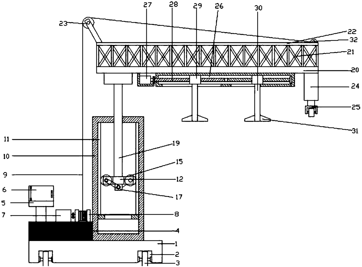
[0004] The current bridge erecting machines are all used to move and orientate the transport of goods on bridges built. This equipment has great limitations and is very restrictive in use, which makes people use it very unchanged.

Method used


Image

  • Liftable single-track bridge erecting machine
  • Liftable single-track bridge erecting machine
  • Liftable single-track bridge erecting machine

Examples


Embodiment Construction

[0019] It should be noted that, in the case of no conflict, the embodiments of the present invention and the features in the embodiments can be combined with each other.

[0020] In describing the present invention, it should be understood that the terms "center", "longitudinal", "transverse", "upper", "lower", "front", "rear", "left", "right", " The orientations or positional relationships indicated by "vertical", "horizontal", "top", "bottom", "inner" and "outer" are based on the orientations or positional relationships shown in the drawings, and are only for the convenience of describing the present invention and Simplified descriptions, rather than indicating or implying that the device or element referred to must have a particular orientation, be constructed and operate in a particular orientation, and thus should not be construed as limiting the invention. In addition, the terms "first", "second", etc. are used for descriptive purposes only, and should not be understood ...


PUM


Abstract

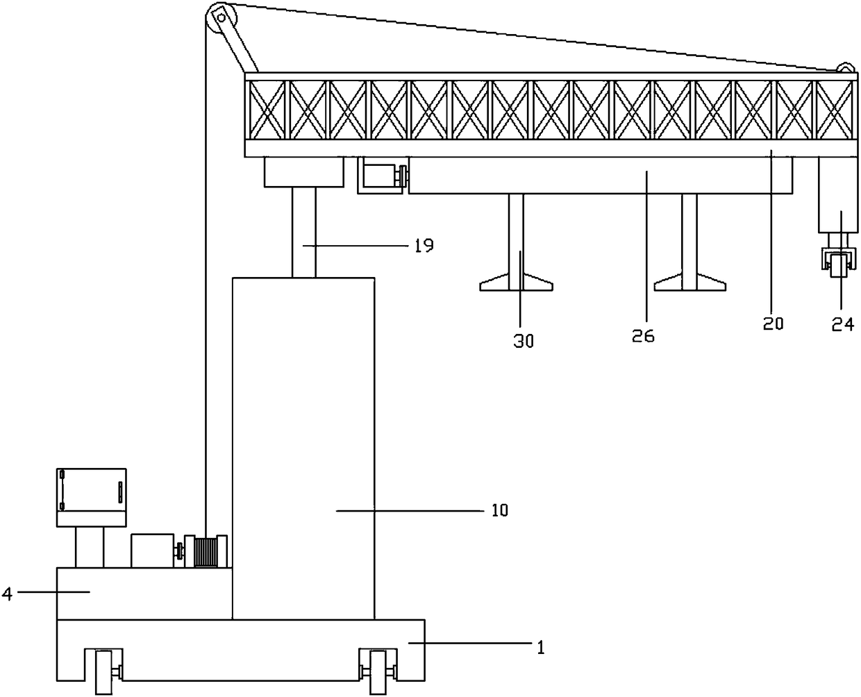
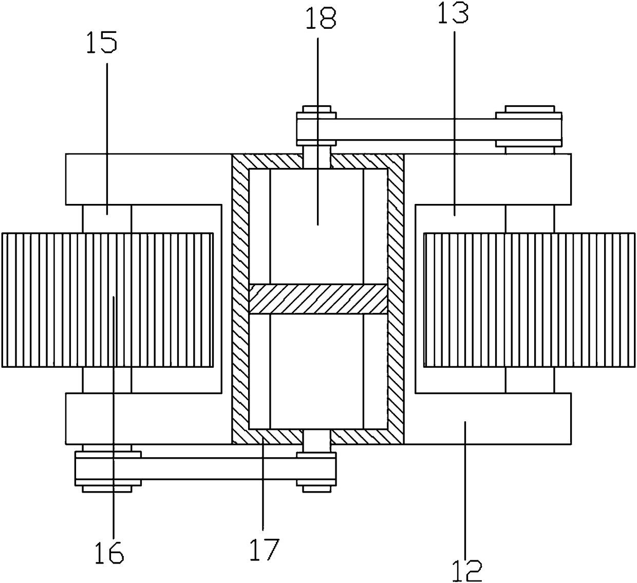
The invention discloses a liftable single-track bridge erecting machine. The liftable single-track bridge erecting machine comprises a base; a counterweight block is arranged at the left end of the upper side of the base; a first motor is arranged on the right side of a control console; a connecting roller is arranged on the right side of the first motor; a steel wire rope is wound on the connecting roller; a supporting pipe is arranged at the upper end of the right side of the counterweight block; racks are arranged at the left and right ends of the interior of the supporting pipe; a connecting block is arranged at the lower end between the racks; a telescopic rod is arranged on the upper side of the connecting block; a supporting plate is arranged on the upper side of the telescopic rod;a reinforcing frame is arranged on the upper side of the supporting plate; a top plate is arranged on the upper side of the reinforcing frame; an electric telescopic rod is arranged at the right endof the lower side of the supporting plate; rollers are arranged on the lower side of the electric telescopic rod; a slide groove is formed in the lower side of the supporting plate; a third motor is arranged on the left side of the slide groove; a lead screw is arranged on the right side of the third motor; slide blocks are arranged at the left and right ends of the lead screw; clamping rods are arranged on the lower sides of the slide blocks; and projections are arranged at the lower ends of the left and right sides of the clamping rods. According to the liftable single-track bridge erectingmachine, the movement of equipment and connection between bridge bodies can be effectively made convenient; convenience is provided for people and the use of the equipment; and the utilization rate ofthe equipment is increased.

Description

technical field [0001] The invention relates to bridge construction equipment, in particular to a liftable single track bridge erecting machine. Background technique [0002] Bridges generally refer to structures erected on rivers, lakes and seas to allow vehicles and pedestrians to pass smoothly. In order to adapt to the modern high-speed development of the transportation industry, bridges are also extended to buildings that cross mountain streams, poor geology or meet other transportation needs to make traffic more convenient. A bridge is generally composed of a superstructure, a substructure, a support and ancillary structures. The superstructure is also called a bridge span structure, which is the main structure for crossing obstacles; the substructure includes abutments, piers and foundations; Or the force transmission device installed at the supporting place of the bridge abutment; the auxiliary structures refer to the bridge head board, conical slope protection, bank...

Claims


Application Information

Patent Timeline
Patent Type & Authority Applications(China)
IPC IPC(8): E01D21/00
CPCE01D21/00
Inventor 项广力马溢坚童巨苍童国柱杨克旺
Owner ZHEJIANG ZHONGJIAN ROAD & BRIDGE EQUIP
Learn More