Multifunctional table used for hotel

A multifunctional, table technology applied in the field of furniture

Active Publication Date: 2016-11-16
重庆展成家俱制造有限公司
View PDF8 Cites 1 Cited by
  • Summary
  • Abstract
  • Description
  • Claims
  • Application Information

AI Technical Summary

Problems solved by technology

[0004] The present invention intends to provide a multifunctional table used in hotels to solve the problem that the existing multifunctional tabl

Method used


Image

  • Multifunctional table used for hotel
  • Multifunctional table used for hotel

Examples


Embodiment Construction

[0016] The present invention will be described in further detail below by means of specific embodiments:

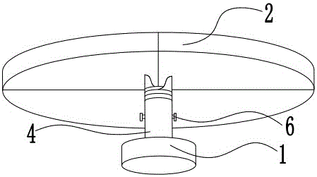
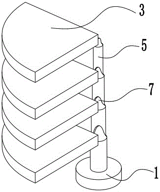
[0017] The reference signs in the accompanying drawings are: support seat 1, table top 2, fan 3, support column 4, sleeve 5, pin 6, protrusion 7.

[0018] Such as figure 1 and figure 2 As shown, the multifunctional table used in hotels in this program includes a support seat 1, a support column 4 and a table top 2 that are sequentially clamped from bottom to top; the support column 4 includes four sequentially socketed sleeves 5; each A sleeve 5 includes a tubular portion and a protruding portion 7 integrally formed with the tubular portion above the tubular portion and gradually protruding upward. The desktop 2 includes four right-angle fan-shaped sectors 3 spliced ​​together; each sector 3 is connected with a protrusion 7 of a sleeve 5; the length of each sleeve 5 decreases successively from the inside to the outside.

[0019] Two adjacent sleeve pipes 5 each have a...


PUM


Abstract

The invention discloses a multifunctional table used for a hotel. The table comprises a supporting base and a table top arranged on the supporting base. A telescoping support column is connected between the supporting base and the table top. The support column comprises a plurality of sleeves which are sleeved with each other in sequence. The table top comprises a plurality of sectors which are spliced together. Each sector is fixedly connected with one sleeve. The lengths of sleeves reduce in sequence from inside out. The table can be changed into a desk or a storage rack according to requirement of a hotel, and the table is convenient to use.

Description

technical field [0001] The invention relates to the field of furniture, in particular to a multifunctional table used in hotels. Background technique [0002] Tables are one of the most commonly used furniture. There are many shapes of tables, but their main function is to support objects. The table generally includes a support base and a desktop arranged on the support base for people to operate and use. In order to develop and utilize the table better, a variety of multifunctional tables have been developed now. Some of these multifunctional tables increase other functions of the table except the basic support by adding some other mechanisms, such as the function of placing specific items, the function of being convenient to move or the functions of expanding the use area and the like. None of the changes made to these multifunctional tables alter the original structure of the table. [0003] However, for a hotel with a large passenger flow and different customer needs...

Claims


Application Information

Patent Timeline
IPC IPC(8): A47B85/06
CPCA47B85/06
Inventor 龙必任
Owner 重庆展成家俱制造有限公司
Why Eureka
Try Eureka