Magnetic recording/reproducing device

Inactive Publication Date: 2005-06-21
HITACHI GLOBAL STORAGE TECH JAPAN LTD
View PDF7 Cites 31 Cited by
  • Summary
  • Abstract
  • Description
  • Claims
  • Application Information

AI Technical Summary

Benefits of technology

[0008]Moreover, by changing a frequency relative to the adjacen

Problems solved by technology

However, the track density becomes increasingly higher, and it is more difficult to narrow the read head track width from the viewpoint of a head manufacturing and the improvement of read head sensitivity.
Accordingly, it is forecasted that it becomes difficult in the

Method used


Image

  • Magnetic recording/reproducing device
  • Magnetic recording/reproducing device
  • Magnetic recording/reproducing device

Examples


embodiment 1

(Embodiment 1)

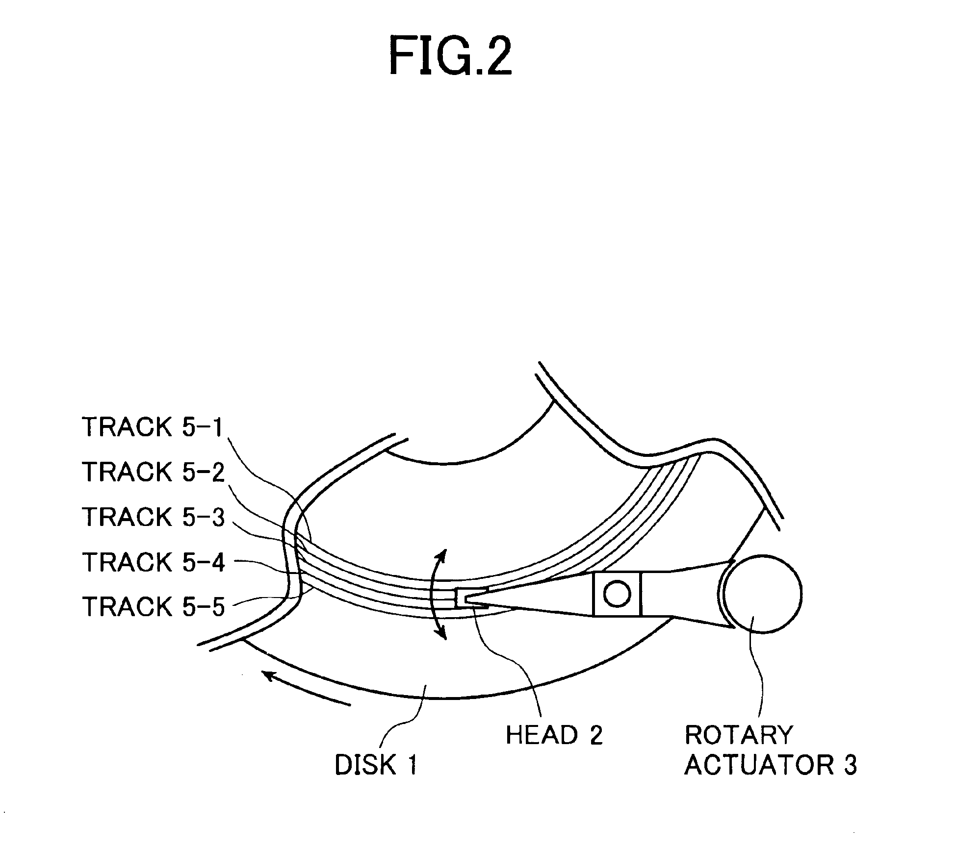
[0025]The present invention will be described while taking the case of a magnetic disk device. A side view of the magnetic disk device is shown in FIG. 1. The magnetic disk device has disk (1-1 to 1-3, a head (2), a rotary actuator (3) and a spindle motor (4). The disk (1) is rotated by the spindle motor (4), and recording of data onto the disk (1) and reproducing of the data recorded are performed by the head (2). The head (2) is driven by the rotary actuator (3), and positioned at an optional position on the disk (1). For this reason, a plurality of tracks (5-1 to 5-5) exist on the disk as shown in FIG. 2, and the head (2) is moved onto any track by the rotary type actuator (3), thus performing the recording / reproducing operation. Servo sectors (6) in which recorded information for positioning the head exist discretely as shown in FIG. 3, and data sectors (7) for recording data exist plurality between the servo sectors (6). The disk is usually divided into several zo...

embodiment 2

(Embodiment 2)

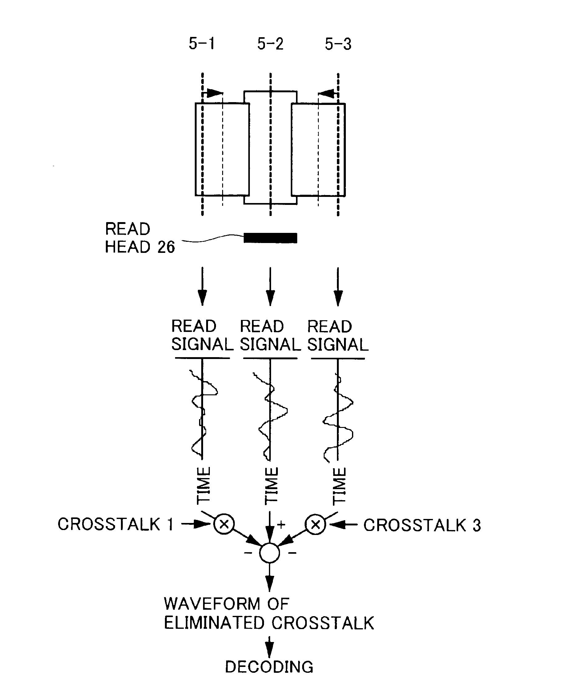
[0028]The write frequency is changed for each one track as shown in FIG. 8. At this time, spectrum of a read back signal of the PLL pattern has frequency peaks (12, 13), respectively, at the positions corresponding to the PLL pattern frequency (F1 / 2) of the read-purposed track (5-3) and the PLL pattern frequency (F2 / 2) of the adjacent tracks (5-2, 5-4), as shown in FIG. 9. Herein, it is assumed that a position of the read head is x, an intensity of the read-purposed track signal at the position x is S1(x) and a crosstalk amount is S2(x). When a crosstalk value at this time is expressed by S2(x)S1(x), the relation between the position x of read head and the crosstalk value S2(x)S1(x) is illustrated so as to have a convex shape with a vertex directed downward as shown in FIG. 10. At the position of x1+Δx, the crosstalk value becomes S2(xl+Δx) / S1(x1+Δx). Assuming that S2(x1) / S1(x1)−S2(x1+Δx) / S1(x1+Δx) is equal to CT(x1, Δx), if CT(x1, Δx)>0 is satisfied when the read head...

embodiment 3

(Embodiment 3)

[0030]In the embodiments 1 and 2, when data straddling over the plurality of tracks is recorded, the head seeks tracks having the same write frequency, thus recording the data thereon. Specifically, in the case of the embodiment 1, when the first portion of the data Is recorded onto the track (5-1) recorded with the write frequency F1 and when all of a series of data cannot be recorded onto the track (5-1) as shown in FIG. 12, the head is allowed to seek the track (5-4) recorded with the same write frequency F1 as the track (5-1), and data which could not be recorded onto the track (5-1) is recorded onto the track (5-4).

[0031]Furthermore, in the case of the embodiment 2, as shown in FIG. 13, the first portion of the data is recorded onto the track (5-1) recorded with the write frequency F1, all of a series of data is not recorded onto the track (5-1), the head is allowed to seek the track (5-3) recording with the same write frequency F1 as the track (5-1), and data whi...


PUM


Abstract

The invention relates to a magnetic recording/reproducing device in which a reproduce head is positioned where the crosstalk between adjacent tracks in a magnetic disk is minimized to maintain an adequate transfer rate in a system involving great crosstalk. The removal of crosstalk ensures the reproduction of the recorded data and thus increases the reliability of the magnetic recording/reproducing device. The magnetic recording/reproducing device according to this invention includes a magnetic disk on which a plurality of tracks are concentrically formed, and data are recorded at different frequencies on adjacent tracks.

Description

TECHNICAL FIELD[0001]The present invention relates to a magnetic recording / reproducing apparatus capable of reducing influences of crosstalks between adjacent tracks in a magnetic recording medium, which has functions to detect the crosstalks, to control a head position and to remove crosstalk components in a read back signal.BACKGROUND ART[0002]Design of a magnetic disk device has heretofore been made so as not to produce problems of crosstalks by determining a write head track width, a read head track width and an erase and width properly. Particularly, the read head track width must be made small to suppress the crosstalks. However, the track density becomes increasingly higher, and it is more difficult to narrow the read head track width from the viewpoint of a head manufacturing and the improvement of read head sensitivity. Accordingly, it is forecasted that it becomes difficult in the future to suppress the crosstalk to be sufficiently low. If the crosstalk becomes significant...

Claims


Application Information

Patent Timeline
IPC IPC(8): G11B20/14G11B5/02G11B5/00G11B5/012G11B21/10G11B5/09G11B5/596
CPCG11B5/00G11B5/012G11B5/02G11B5/596G11B20/1403G11B21/106G11B2005/001G11B5/09
Inventor ZAITSU, HIDEKIHAMAGUCHI, TAKEHIKOTOMIYAMA, FUTOSHI
Owner HITACHI GLOBAL STORAGE TECH JAPAN LTD
Why Eureka
Try Eureka