Photovoltaic tile mounting device and system

A technology for installing devices and photovoltaic tiles, which is applied in the direction of photovoltaic modules, photovoltaic power generation, and support structures for photovoltaic modules. convenient effect

Inactive Publication Date: 2018-10-02
JIANGSU HANJIA THIN FILM SOLAR SCI & TECH CO LTD
View PDF4 Cites 8 Cited by
  • Summary
  • Abstract
  • Description
  • Claims
  • Application Information

AI Technical Summary

Problems solved by technology

[0004] The photovoltaic tile installation system in the prior art only connects the hanging tile with the protruding screw rod of the screw, and realizes the installation through the pressure generated by the upper photovoltaic tile overlapping the lower photovoltaic tile, which does not have high windproof and earthquake resistance. In the environment of strong wind and strong earthquake, it is easy to be opened

Method used


Image

  • Photovoltaic tile mounting device and system
  • Photovoltaic tile mounting device and system
  • Photovoltaic tile mounting device and system

Examples


Embodiment 1

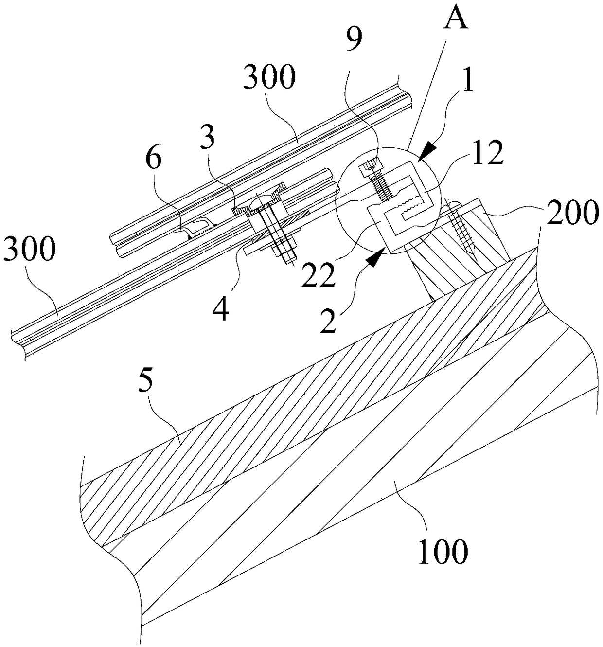
[0041] figure 2 It is a schematic structural diagram of a photovoltaic tile installation device provided in Embodiment 1 of the present invention. Such as figure 2 As shown, the photovoltaic tile installation system mainly includes a first mount 1 and a second mount 2 , the first mount 1 is fixed to the photovoltaic tile 300 , and the second mount 2 is fixed to the tile hanger 200 . The first hanger 1 is connected to the second hanger 2 to fix the photovoltaic tile 300 on the surface 100 to be installed. Specifically, the surface to be installed 100 may be the roof, or other locations of the building. Taking the roof as an example, the surface to be installed 100 is inclined at a relatively large angle. Therefore, in order to prevent photovoltaic tiles from falling and to achieve stronger wind and shock resistance, the first main body 11 and the first hook part 12 arranged on the first main body 11 are included, and the second main body 21 and the first hook part 12 arrang...

Embodiment 2

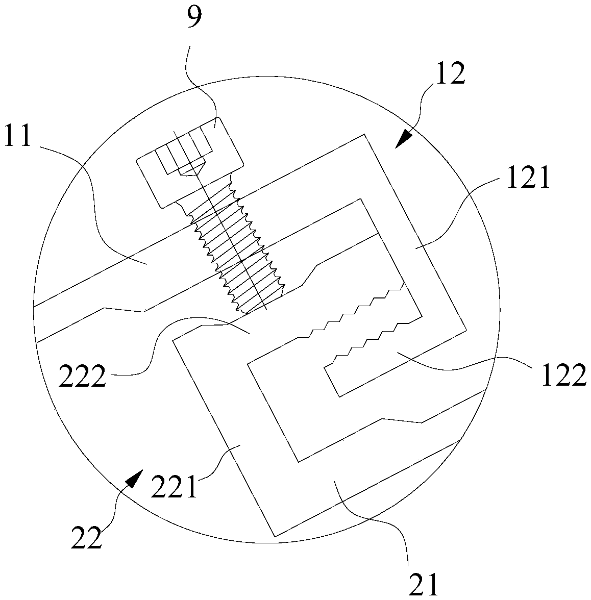
[0048] The photovoltaic tile installation system provided by Embodiment 2 of the present invention, such as Figure 4 As shown, threaded holes are provided at the overlaps of the first bent plate 122 and the second bent plate 222, or through holes are provided on the first bent plate 122, and threaded holes are correspondingly provided on the second bent plate 222. . In actual use, first engage the sawtooth structures on the first bent plate 122 and the second bent plate 222, and insert the fastener 9 from the threaded hole or through hole on the first bent plate 122 into the second bent plate 122. The screw holes on the second bending plate 222 are tightened. During the tightening process, the first hook part 12 and the second hook part 22 are automatically fastened at the hooks. The fastener 9 in the second embodiment can be selected as an external hexagonal bolt. When the connection needs to be disassembled, there is a certain space for a wrench outside, and the bolt can b...

Embodiment 3

[0050] The photovoltaic tile installation system provided by Embodiment 3 of the present invention, specifically, as Figure 5 As shown, the first hook part 12 and the second hook part 22 are not provided with the first bent plate 122 and the second bent plate 222, and the sawtooth structure is directly set on the first connecting plate 121, and on the second connecting plate 221 The sawtooth structure is provided, and the sawtooth structure on the first connecting plate 121 can engage with the sawtooth structure on the second connecting plate 221 to realize the hooking of the first hook part 12 and the second hook part 22 . Further, threaded holes are provided on the sawtooth structure on the first connecting plate 121 and the sawtooth structure on the second connecting plate 221, or through holes are set on the sawtooth structure on the first connecting plate 121, and on the second connecting plate 221 Threaded holes are provided on the sawtooth structure on the top, and the...


PUM


Abstract

The invention discloses a photovoltaic tile mounting device and system, and relates to the technical field of photovoltaic power generation. The photovoltaic tile mounting device comprises first hanging-connection pieces and second hanging-connection pieces; each first hanging-connection piece comprises a first main body and a first hook part arranged on the first main body, and the first main bodies and photovoltaic tiles are fixed; and each second hanging-connection piece comprises a second main body and a second hook part arranged on the second main body, the second main bodies are fixed tothe to-be-mounted face, and the first hook parts and the second hook parts can be hooked and relatively fixed. The photovoltaic tile mounting system comprises the photovoltaic tiles, supporting tilesand the photovoltaic tile mounting device, wherein the photovoltaic tiles and the supporting tiles arranged at intervals, the photovoltaic tiles are mounted on the to-be-mounted face through the photovoltaic tile mounting device, the photovoltaic tiles are in overlapping connection with the adjacent supporting tiles, and at the overlapping position, the photovoltaic tiles are located on the upperportions of the supporting tiles. The photovoltaic tile mounting system and photovoltaic tile assemblies are simple in structure, convenient to mount and dismount, high in wind prevention and earthquake resistance, and wide in application range.

Description

technical field [0001] The invention relates to the technical field of photovoltaic power generation, in particular to a photovoltaic tile installation device and a photovoltaic tile installation system. Background technique [0002] Solar thin-film power generation surface tiles (referred to as photovoltaic tiles) have been widely used in the field of building photovoltaic integration technology. The photovoltaic tiles are installed on the roof through the installation system, so that the building itself uses green and environmentally friendly solar energy resources to generate electricity. In the photovoltaic tile installation system, how to improve the wind and earthquake resistance of photovoltaic tiles has become an important issue. [0003] The structure of the photovoltaic tile installation system in the prior art is as follows: figure 1 As shown, a plurality of photovoltaic tiles 300' are overlapped with each other to form a photovoltaic tile roof, and each photovo...

Claims


Application Information

Patent Timeline
Patent Type & Authority Applications(China)
IPC IPC(8): E04D13/18H02S20/25
CPCE04D13/00H02S20/25Y02B10/10Y02E10/50
Inventor 廉军建郭海利徐智伟
Owner JIANGSU HANJIA THIN FILM SOLAR SCI & TECH CO LTD
Why Eureka
Try Eureka