Corrugated pipe and assembling method

A corrugated pipe and pipe body technology, which is applied in the field of corrugated pipe and assembly, can solve the problems that the outside of the pipe body is easy to bear pressure, damage and deform, two sections of the pipe body fall off the opening, and the fixation is not firm, etc. The inner wall is tight and the effect of preventing water seepage

Inactive Publication Date: 2018-10-02
江苏星河集团有限公司
View PDF5 Cites 0 Cited by
  • Summary
  • Abstract
  • Description
  • Claims
  • Application Information

AI Technical Summary

Problems solved by technology

[0002] Bellows are mainly divided into metal bellows and PE bellows. In daily life, PE bellows are a relatively commonly used pipe. PE bellows are plastic protective sleeves extruded from polyethylene, because their inside and outside are ring-shaped. Corrugated pipes are also called corrugated pipes, which are mainly used in municipal engineering, drainage of residential areas; highway pipes; It needs to be buried underground. Under the pressure of the soil, the outside of the pipe body is easy to bear pressure, damage and deform, and the inside of the pipe body is relatively easy to rupture because it is pressed by water or other fluids for a long time. At the same time, when the existing bellows are installed, the pipe The splicing between the bodies is usually made of corrugated concave-convex structures to fit each other, and the effect of friction is used to fix the connection of the two pipes. This is not a firm fixation. Once the joint is deformed, it is easy to cause the two pipes to fall off and open, causing water seepage, etc. situation, therefore, the present invention proposes a bellows and assembly method to solve the problems in the prior art

Method used


Image

  • Corrugated pipe and assembling method
  • Corrugated pipe and assembling method
  • Corrugated pipe and assembling method

Examples


Embodiment Construction

[0023] In order to deepen the understanding of the present invention, the present invention will be further described below in conjunction with the examples, which are only used to explain the present invention, and do not constitute a limitation to the protection scope of the present invention.

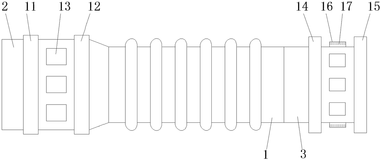
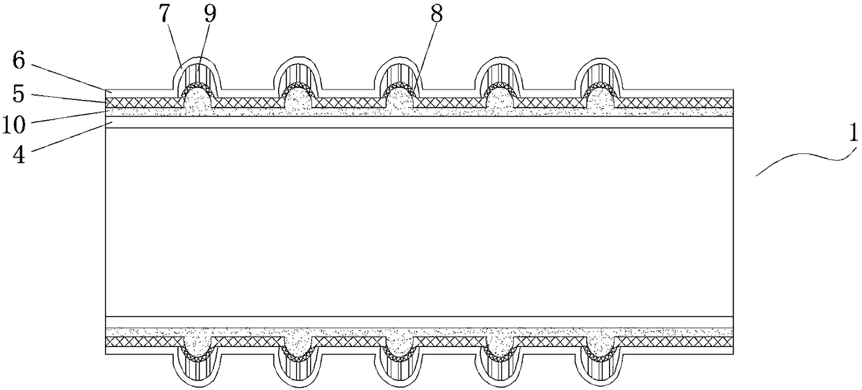
[0024] according to figure 1 , 2 As shown in . The side is provided with a socket pipe 3, the pipe body 1 includes an inner pipe 4, a wire pipe 5 and an outer pipe 6, the outer side of the inner pipe 4 is provided with a wire pipe 5, and the outer side of the wire pipe 5 is provided with an outer pipe 6. The outside of the outer tube 6 is provided with an outer tube protrusion 7, the outer side of the iron wire tube 5 is provided with an iron tube protrusion 8, and a supporting rib is provided between the iron wire tube protrusion 8 and the outer tube protrusion 7 9. The heat insulating material 10 is filled between the inner pipe 4 and the wire pipe 5, and the inside of the receiv...


PUM


Abstract

The invention discloses a corrugated pipe and an assembling method. The corrugated pipe comprises a pipe body, an adapting pipe and an inserting pipe; the adapting pipe is arranged on one side of thepipe body; the inserting pipe is arranged on the other side of the pipe body; the pipe body comprises an inner pipe, an iron wire pipe and an outer pipe; the iron wire pipe sleeves the inner pipe; theouter pipe sleeves the iron wire pipe; outer pipe bulges are arranged on the outer side of the outer pipe; iron wire pipe bulges are arranged on the outer side of the iron wire pipe; supporting ribsare arranged between the iron wire pipe bulges and the outer pipe bulges; and the part between the inner pipe and the iron wire pipe is filled with a heat insulating material. The supporting ribs arearranged between the outer pipe bulges and the iron wire pipe bulges, so that the bearing pressure outside the pipe body is improved; the iron wire pipe bulges correspond with the outer pipe bulges toform vacuum cavities, so that the inner wall of the pipe body is tighter, the buffering effect is improved, and the possibility of damage and deformation is low; and the toughness of the inner pipe is improved due to the compressed effect of the iron wire pipe, and the possibility of rupture is low.

Description

technical field [0001] The invention relates to the technical field of pipes, in particular to a corrugated pipe and an assembly method. Background technique [0002] Bellows are mainly divided into metal bellows and PE bellows. In daily life, PE bellows are a relatively commonly used pipe material. PE bellows are plastic protective sleeves extruded from polyethylene, because their inside and outside are ring-shaped. Corrugated pipes are also called corrugated pipes, which are mainly used in municipal engineering, drainage of residential areas; highway pipes; It needs to be buried underground. Under the pressure of the soil, the outside of the pipe body is easy to bear pressure, damage and deform, and the inside of the pipe body is relatively easy to rupture because it is pressed by water or other fluids for a long time. At the same time, when the existing corrugated pipe is installed, the pipe The splicing between the bodies is usually made of corrugated concave-convex str...

Claims


Application Information

Patent Timeline
Patent Type & Authority Applications(China)
IPC IPC(8): F16L11/112F16L57/02F16L21/08
CPCF16L11/112F16L21/08F16L57/02
Inventor 匡红卫尚武银
Owner 江苏星河集团有限公司
Why Eureka
Try Eureka