Calculation method and apparatus for reinforcement ratio of concrete unit

A calculation method and concrete technology, applied in calculation, design optimization/simulation, special data processing applications, etc., can solve problems such as concrete cannot provide data support

Active Publication Date: 2018-10-02
CHINA INST OF WATER RESOURCES & HYDROPOWER RES +1
4 Cites 6 Cited by

AI-Extracted Technical Summary

Problems solved by technology

The methods in the prior art are only applicable to the calculation of the reinforcement ratio of simple buildings such as beams, columns, and slabs, and are not applicable to complex building models and ...

Abstract

The invention provides a calculation method and apparatus for a reinforcement ratio of a concrete unit. The method comprises the steps of obtaining a concrete model and a reinforcement model of a target building; dividing the concrete model by adopting a preset geometric unit to obtain a concrete finite element model, wherein the concrete finite element model comprises M concrete units, and M is an integer greater than 0; dividing the reinforcement model by adopting a preset linear unit to obtain a reinforcement finite element model, wherein the reinforcement finite element model comprises N reinforcement units, and N is an integer greater than 0; and according to position information of the reinforcement units and position information of the concrete units, obtaining the reinforcement ratio of each concrete unit. The calculation method and apparatus can be suitable for calculation of the reinforcement ratio of the concrete unit in more complex engineering, and can provide data supportfor subsequent reinforcement concrete combined effect finite element calculation analysis.

Application Domain

Geometric CADDesign optimisation/simulation +1

Technology Topic

RebarReinforced concrete +4

Image

  • Calculation method and apparatus for reinforcement ratio of concrete unit
  • Calculation method and apparatus for reinforcement ratio of concrete unit
  • Calculation method and apparatus for reinforcement ratio of concrete unit

Examples

  • Experimental program(1)

Example Embodiment

[0039] In order to make the objectives, technical solutions, and advantages of the embodiments of the present invention clearer, the technical solutions in the embodiments of the present invention will be described clearly and completely in conjunction with the accompanying drawings in the embodiments of the present invention. Obviously, the described embodiments It is a part of the embodiments of the present invention, not all the embodiments. Based on the embodiments of the present invention, all other embodiments obtained by those of ordinary skill in the art without creative work shall fall within the protection scope of the present invention.
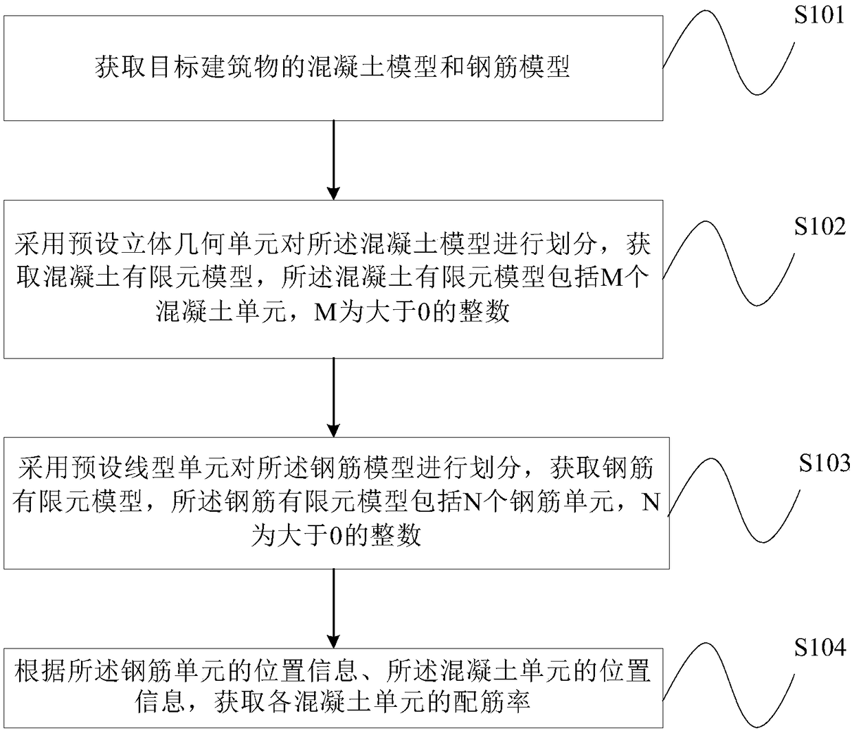
[0040] figure 1 It is a schematic flow chart of Embodiment 1 of the method for calculating the reinforcement ratio of concrete elements provided by the present invention, such as figure 1 As shown, the method includes:
[0041] S101. Obtain a concrete model and a steel reinforcement model of the target building.
[0042] A separate reinforced concrete model is established in the overall coordinate system according to the entity target building, that is, the concrete model and the steel reinforcement model are respectively established in the overall coordinate system according to the entity target building. Moreover, it is assumed in this model that the concrete and steel bars are well bonded, and there will be no relative slippage.
[0043] S102. Divide the concrete model by using preset three-dimensional geometric units to obtain a concrete finite element model. The concrete finite element model includes M concrete units, and M is an integer greater than 0.
[0044] Optionally, the aforementioned preset solid geometric unit may be a 3D 8-node hexahedral unit, a 3D 6-node triangular prism unit, or a 3D 4-node tetrahedral unit. It should be noted that the aforementioned preset solid geometric unit may also be other solid geometric units. It is not limited to the above three three-dimensional geometric units, which is not limited in the present invention.
[0045] When dividing the above concrete model to obtain the concrete finite element model, the size of the preset solid geometric unit should not be too large. The larger the size of the preset solid geometric unit, the smaller the calculation, but the lower accuracy of the result. The smaller the size of the preset three-dimensional geometric unit, the higher the accuracy of the calculation result, but the larger the amount of calculation. Therefore, the concrete model of different target buildings can be divided according to the actual situation by selecting the appropriate size of the three-dimensional geometric unit. Obtain the finite element model. Optionally, in an implementation manner, the size of each side length of the preset three-dimensional geometric unit may be 1 to 2 meters.
[0046] Further, the above-mentioned concrete finite element model includes M concrete elements, and each concrete element has multiple nodes. For example, if a cube with a side length of 1 meter is used to divide the concrete model, then each concrete unit has 8 nodes.
[0047] It should be noted that in practical applications, one or more solid geometric units can be selected according to the actual situation to divide the concrete model of the target building, which means that different areas of the concrete model of the target building can be selected differently. The solid geometric unit is divided to make the obtained concrete finite element model more accurate, which is not limited in the present invention.
[0048] S103: Divide the steel bar model by using a preset linear unit to obtain a steel bar finite element model. The steel bar finite element model includes N steel bar units, and N is an integer greater than 0.
[0049] Because the steel bar is a slender material, its transverse shear strength can usually be ignored, and it is considered that it only bears the axial force in the longitudinal direction. Therefore, the steel bar model is divided by linear elements to obtain the steel bar finite element model. For example: using three-dimensional 2-node line elements to divide the steel bar model.
[0050] Among them, the smaller the size of the linear unit, the higher the accuracy of the calculated result, the larger the size of the linear unit, the lower the accuracy of the result. In order to finely simulate the combined effect of reinforced concrete and reduce calculation errors, optionally in an implementation manner, the size of the linear unit may be 5% of the size of the solid geometric unit of the concrete. For example, when a cube with a side length of 1 meter is used to divide the concrete model, the size of the linear unit is 0.05 meters.
[0051] Further, the above-mentioned steel finite element model includes N steel reinforcing elements, and each reinforcing steel element includes two end points. And number all the endpoints of the above N steel reinforcement elements.
[0052] S104. Obtain the reinforcement ratio of each concrete unit according to the position information of the reinforcing steel unit and the position information of the concrete unit.
[0053] In this embodiment, by acquiring the concrete model and the steel bar model of the target building, the concrete model is divided by using preset three-dimensional geometric units to obtain the concrete finite element model. The concrete finite element model includes M concrete units, where M is An integer greater than 0, the steel bar model is divided by a preset linear unit to obtain a steel bar finite element model. The steel bar finite element model includes N steel bar units. N is an integer greater than 0. The position information, the position information of the concrete unit, and the reinforcement ratio of each concrete unit are obtained. That is to say, the concrete finite element model and the steel finite element model of the target building are obtained separately, and the finite element isoparametric transformation shape function and the Newton iteration method are used for calculation, so as to obtain the reinforcement ratio of the concrete element, which can be applied to more The calculation of the reinforcement ratio of concrete elements in many complex projects, and the obtained reinforcement ratio of the concrete elements of the target building can provide data support for the subsequent finite element calculation and analysis of the combined action of reinforced concrete.
[0054] Optionally, in an implementation manner, in the foregoing embodiment, according to the position information of the reinforcing bar unit and the position information of the concrete unit, obtaining the reinforcement ratio of each concrete unit may involve the following process:
[0055] First, according to the shape function of the concrete unit, the position information of the steel bar unit, and the position information of the concrete unit, the mapping relationship between the steel bar unit and the concrete unit is established.
[0056] Specifically, according to the shape function of the concrete unit and the position information of the concrete unit, the concrete unit is isoparametrically transformed, and the Newton iteration method is used for calculation, and the local coordinates of the end points of each steel bar unit are calculated.
[0057] A mapping relationship is established between the concrete unit where the local coordinates of the end point of the reinforcement unit are located and the reinforcement unit.
[0058] What needs to be explained here is that when obtaining the local coordinates of the end point of the reinforcing bar unit in a certain concrete unit, the local coordinate system is first established according to the concrete unit. For example, after the concrete model is divided by three-dimensional eight-node hexahedral elements, the corresponding schematic diagram of the concrete element and the schematic diagram of the local coordinate system established according to the concrete element are as follows: figure 2 As shown, of course, it is also possible to establish a local coordinate system with other nodes in the concrete unit as the origin, and establishing different local coordinate systems for the same concrete unit does not affect the calculation result. When other types of solid geometric units are used to divide the concrete model, the corresponding concrete unit and the method of establishing the local coordinate system based on the concrete unit are similar to the existing methods, and the present invention will not be described in detail here.
[0059] In practical applications, based on the finite element isoparametric transformation of concrete elements, the corresponding local coordinates are calculated according to the coordinates of the end points of the reinforcement elements in the global coordinate system, and then the local coordinates of the end points of the reinforcement elements are determined in the concrete Within the unit.
[0060] The coordinate conversion from the elements with regular geometric shapes in local coordinates to the elements with distorted geometric shapes in global coordinates is as follows:
[0061]
[0062] Among them, m is the number of nodes of the concrete element, x i , Y i ,z i Is the coordinate value of a concrete element node in the overall coordinate, ξ, η, ζ are the local coordinate system, N i (ξ,η,ζ) is the shape function expressed in local coordinates, N i (ξ, η, ζ) can be obtained from books about finite element method according to the preset solid geometric unit type.
[0063] According to formula (1), let:
[0064]
[0065] It is known that the overall coordinates of the endpoint of one of the steel reinforcement elements are Use equation Find the local coordinates of the end point of the reinforcement element in the concrete element
[0066] make:
[0067]
[0068] Solve:
[0069]
[0070] According to Newton's iteration method:
[0071]
[0072] Among them, in formula (5) Is the iteration result of step n+1, Is the iteration result of the nth step.
[0073]
[0074]
[0075] make:
[0076]
[0077] Among them, in formula (8) Called the Jacobi matrix, for The inverse matrix.
[0078] will Substitute into (5), (6), (8) to get:
[0079]
[0080] If satisfied |ξ n+1 -ξ n |≤ε,|η n+1 -η n |≤ε,|ζ n+1 -ζ n |≤ε, the iteration ends, ε is the set convergence tolerance, then the overall coordinates are The local coordinates of the end point of the reinforcing bar unit in the concrete unit are:
[0081]
[0082] Further, the judgment is made according to the local coordinates of the end point of the reinforcing bar unit in the concrete unit and the position information of the concrete unit.
[0083] If the local coordinates of the end point of the steel bar unit are in the concrete unit, a mapping relationship between the end number of the steel bar unit and the number of the concrete unit is established.
[0084] If the local coordinates of the end point of the reinforcing bar unit are not in the concrete unit, the next concrete unit is traversed until the concrete unit corresponding to the end point of the reinforcing bar unit is found, and the corresponding mapping relationship is established.
[0085] It should be noted that the method for judging whether the local coordinate of the end point of the reinforcing bar unit is in the concrete unit by the coordinate position is similar to the prior art, and the present invention will not be described in detail here.
[0086] Optionally, in an implementation manner, if the local coordinates of the end points of the reinforcing bar unit are not in the concrete unit, the traversal is performed in the order of the concrete unit numbers from small to large.
[0087] Further, according to the mapping relationship between the steel bar unit and the concrete unit, traverse the steel bar units with the mapping relationship of each concrete unit.
[0088] According to the number of end points of each concrete unit in the corresponding concrete unit among the steel bar units in which each concrete unit has a mapping relationship, the reinforcement ratio of each concrete unit is obtained.
[0089] Specifically, for a certain concrete unit, the reinforcement unit is traversed, and the number of the reinforcement unit endpoints of the reinforcement unit in the concrete unit is determined according to the mapping relationship established above. If the reinforcement unit is located in the corresponding concrete unit If the number of endpoints in the unit is 1, then the volume of the reinforcement unit in the x, y, and z directions in the corresponding concrete unit is 1/2 of the actual volume of the reinforcement unit and the direction vector of the reinforcement unit is in the x, y, and z directions The product of the components; if the number of endpoints of the reinforcement unit in the corresponding concrete unit is 2, the volume of the reinforcement unit in the x, y, and z directions in the corresponding concrete unit is the actual volume of the reinforcement unit and the direction vector of the reinforcement unit at x The product of the components in the, y, and z directions. When the traversal of the reinforcement unit is completed, the volumes in the x, y, and z directions of all the reinforcement units in the concrete unit are added up and divided by the volume of the concrete unit. The calculated result is the concrete unit along x, y, and Reinforcement ratio in z direction ρ x , Ρ y , Ρ z.
[0090] It should be noted that when the traversal is performed, if there is no mapping relationship between the steel bar unit and the concrete unit, the volume of the steel bar unit in the concrete unit is 0.
[0091] It should be noted that the actual volume of the steel bar unit is the product of the cross-sectional area of ​​the steel bar unit and the length of the linear unit.
[0092] Further, starting to traverse each of the concrete units in the concrete finite element model, until the reinforcement ratios of all the concrete units are obtained, and ending the traversal of the concrete units.
[0093] Optionally, a traversal method is to traverse the reinforcement unit number and the concrete unit number in ascending order.
[0094] For example, if the concrete finite element model has M concrete elements, and the steel finite element model has N steel reinforcement elements, then for the first concrete element, start to traverse the N steel reinforcement elements in the steel finite element model. First, according to the mapping relationship, determine the number of the end points of the first reinforcement unit in the first concrete unit, and obtain the corresponding reinforcement in the x, y, and z directions of the first reinforcement unit in the first concrete unit The volume of the element, and then judge the number of the end points of the second reinforcement element in the first concrete element according to the mapping relationship, and obtain the corresponding x, y, and z directions of the second reinforcement element in the first concrete element The volume of the steel bar unit, and so on, obtain the corresponding steel bar unit volume of the N steel bar units in the x, y, and z directions in the first concrete unit. Then sum the corresponding steel volume in the x, y, and z directions of the N steel reinforcement elements in the first concrete element in the reinforcement finite element model, and divide by the volume of the first concrete element to obtain the first concrete The reinforcement ratio of the unit in the x, y, and z directions.
[0095] Further, for the second concrete unit, start to traverse all the N steel reinforcement units in the finite element model of the steel reinforcement, and obtain the reinforcement ratio of the second concrete unit in the x, y, and z directions through the same method described above. By analogy, traverse the M concrete units in the concrete finite element model to obtain the reinforcement ratios of the M concrete units in the x, y, and z directions.
[0096] It should be noted that in the present invention, the steel bar unit and the concrete unit can also be traversed in other order, for example: the steel bar unit number and the concrete unit number can be traversed in descending order, which is not limited in the present invention. .
[0097] In the foregoing, the reinforcement ratio of each concrete unit is obtained according to the position information of the steel bar unit and the position information of the concrete unit. Another implementation method may be:
[0098] First, according to the shape function of the concrete element and the position information of the concrete element, transform the concrete element isoparametrically, and calculate by using the Newton iteration method to calculate the local coordinates of the end points of each of the reinforcing steel elements;
[0099] According to the local coordinates of the end points of each reinforcing bar unit, it is directly judged whether it is in the concrete unit. If the number of end points of the reinforcing bar unit in the corresponding concrete unit is 1, then the reinforcing bar unit is in the x, y, z direction in the corresponding concrete unit The volume above is the product of 1/2 of the actual volume of the reinforcement unit and the component of the direction vector of the reinforcement unit in the x, y, and z directions; if the number of endpoints of the reinforcement unit in the corresponding concrete unit is 2, the reinforcement unit is The volume corresponding to the x, y, and z directions in the concrete unit is the product of the actual volume of the reinforcement unit and the component of the reinforcement unit direction vector in the x, y, and z directions.
[0100] It should be noted that the method of calculating the local coordinates of the end points of each of the reinforcing bar elements is the same as the foregoing method.
[0101] In this embodiment, the concrete model and the steel bar model of the target building are obtained, and the concrete model is divided using preset three-dimensional geometric units to obtain a concrete finite element model. The concrete finite element model includes M concrete units, and M is greater than An integer of 0, the steel bar model is divided by a preset linear unit to obtain a steel bar finite element model. The steel bar finite element model includes N steel bar units, N is an integer greater than 0, according to the position of the steel bar unit Information, the location information of the concrete unit, and the reinforcement ratio of each concrete unit. That is to say, the concrete finite element model and the steel finite element model of the target building are obtained separately, and the finite element isoparametric transformation shape function and the Newton iteration method are used for calculation, so as to obtain the reinforcement ratio of the concrete element, which can be applied to more The calculation of the reinforcement ratio of concrete elements in many complex projects, and the obtained reinforcement ratio of the concrete elements of the target building can provide data support for the subsequent finite element calculation and analysis of the combined action of reinforced concrete.
[0102] image 3 This is a schematic structural diagram of Embodiment 1 of the device for calculating the reinforcement ratio of concrete units provided by the present invention. The calculation device for the reinforcement ratio of concrete units provided by the present invention can be used to perform figure 1 The technical solution of the method embodiment shown. Such as image 3 As shown, the device for calculating the reinforcement ratio of concrete units provided in this embodiment includes:
[0103] The obtaining module 31 is used to obtain the concrete model and the steel bar model of the target building.
[0104] The first mesh division module 32 is configured to divide the concrete model by using preset three-dimensional geometric units to obtain a concrete finite element model. The concrete finite element model includes M concrete units, and M is an integer greater than 0.
[0105] The second mesh division module 33 is configured to divide the steel bar model by using preset linear units to obtain a steel bar finite element model. The steel bar finite element model includes N steel bar units, and N is an integer greater than 0.
[0106] The calculation module 34 is configured to obtain the reinforcement ratio of each concrete unit according to the position information of the steel bar unit and the position information of the concrete unit.
[0107] The device provided in this embodiment specifically obtains the concrete finite element model and the steel finite element model of the target building respectively, and uses the finite element isoparametric transformation shape function and Newton iteration method to calculate, thereby obtaining the reinforcement ratio of the concrete element , It can be applied to the calculation of the reinforcement ratio of concrete elements in more complex projects, and the obtained reinforcement ratio of the concrete elements of the target building can provide data support for the subsequent finite element calculation and analysis of the combined effect of reinforced concrete.
[0108] In an embodiment of the present invention, the calculation module 34 is further configured to obtain the reinforcement ratio of each concrete unit according to the position information of the steel bar unit and the position information of the concrete unit, according to the concrete The shape function of the unit, the position information of the steel bar unit, and the position information of the concrete unit establish a mapping relationship between the steel bar unit and the concrete unit.
[0109] Specifically, the calculation module 34 is specifically configured to perform isoparametric transformation of the concrete unit according to the shape function of the concrete unit and the position information of the concrete unit, and use Newton iteration method to calculate the end point of each steel bar unit. Local coordinates;
[0110] A mapping relationship is established between the concrete unit where the local coordinates of the end point of the reinforcement unit are located and the reinforcement unit.
[0111] Further, the calculation module 34 is specifically configured to traverse the steel bar units with a mapping relationship between each concrete unit according to the mapping relationship between the steel bar unit and the concrete unit;
[0112] According to the number of end points of each concrete unit in the corresponding concrete unit among the steel bar units in which each concrete unit has a mapping relationship, the reinforcement ratio of each concrete unit is obtained.
[0113] Further, the calculation module 34 is specifically used to calculate the volume of the steel bar unit in the corresponding concrete unit that has a mapping relationship for each concrete unit. If the number of end points of the steel bar unit in the corresponding concrete unit is 1, then the steel bar unit is in The volume in the corresponding concrete unit is 1/2 of the actual volume of the reinforcement unit; if the number of endpoints of the reinforcement unit in the corresponding concrete unit is 2, then the volume of the reinforcement unit in the corresponding concrete unit is the actual volume of the reinforcement unit volume;
[0114] The reinforcement ratio of each concrete unit is obtained according to the volume of the steel bar unit in the corresponding concrete unit with the mapping relationship of each concrete unit.
[0115] Figure 4 This is a schematic structural diagram of Embodiment 2 of the device for calculating the reinforcement ratio of a concrete unit provided by the present invention. The apparatus may include: a memory 401 and a processor 402.
[0116] The memory 401 may be an independent physical unit, and may be connected to the processor 402 through a bus. The memory 401 and the processor 402 may also be integrated together and implemented through hardware.
[0117] The memory 401 is used to store the implementation of the above method embodiment, and the processor 402 calls the program to execute the operation of the method embodiment executed by the above device.
[0118] Optionally, when part or all of the methods in the foregoing embodiments are implemented by software, the foregoing apparatus may also only include a processor. The memory for storing the program is located outside the above-mentioned device, and the processor is connected to the memory through a circuit/wire for reading and executing the program stored in the memory.
[0119] The processor may be a central processing unit (Central Processing Unit, CPU), a network processor (Network Processor, NP), or a combination of a CPU and NP.
[0120] The processor may further include a hardware chip. The aforementioned hardware chip may be an application-specific integrated circuit (ASIC), a programmable logic device (PLD), or a combination thereof. The above-mentioned PLD can be a complex programmable logic device (CPLD), a field-programmable gate array (FPGA), a generic array logic (GAL) or any combination thereof.
[0121] The memory may include volatile memory (volatile memory), such as random-access memory (random-access memory, RAM); the memory may also include non-volatile memory (non-volatile memory), such as flash memory, Hard disk drive (HDD) or solid-state drive (SSD); the storage may also include a combination of the above types of storage.
[0122] A person of ordinary skill in the art can understand that all or part of the steps in the foregoing method embodiments can be implemented by a program instructing relevant hardware. The aforementioned program can be stored in a computer readable storage medium. When the program is executed, it executes the steps including the foregoing method embodiments; and the foregoing storage medium includes: ROM, RAM, magnetic disk, or optical disk and other media that can store program codes.
[0123] Finally, it should be noted that the above embodiments are only used to illustrate the technical solutions of the present invention, but not to limit them; although the present invention has been described in detail with reference to the foregoing embodiments, those of ordinary skill in the art should understand: It is still possible to modify the technical solutions described in the foregoing embodiments, or equivalently replace some or all of the technical features; and these modifications or replacements do not make the essence of the corresponding technical solutions deviate from the technical solutions of the embodiments of the present invention. range.

PUM

no PUM

Description & Claims & Application Information

We can also present the details of the Description, Claims and Application information to help users get a comprehensive understanding of the technical details of the patent, such as background art, summary of invention, brief description of drawings, description of embodiments, and other original content. On the other hand, users can also determine the specific scope of protection of the technology through the list of claims; as well as understand the changes in the life cycle of the technology with the presentation of the patent timeline. Login to view more.
Why Eureka
Try Eureka