Rolling mill pressure head auxiliary dismounting and mounting device and pressure head dismounting method

A technology for indenters and rolling mills, which is applied in the field of auxiliary dismantling equipment for indenters in rolling mills and in the field of indenter disassembly, which can solve problems such as mechanical injury safety, low maintenance efficiency, and hydraulic equipment that cannot be stopped, so as to improve safety and improve disassembly The effect of overhaul efficiency

Inactive Publication Date: 2018-10-09
MCC BAOSTEEL TECH SERVICE
View PDF2 Cites 4 Cited by
  • Summary
  • Abstract
  • Description
  • Claims
  • Application Information

AI Technical Summary

Problems solved by technology

[0003] Disadvantages of the above method: 1) The removal of the indenter is realized through the action of the on-site equipment. After each equipment action, the on-site equipment needs to be re-listed for power failure, and there are potential safety hazards of mechanical damage for multiple actions; 2) Pumping the support roller When the on-site hydraulic equipment cannot stop
Due to non-stop maintenance of hydraulic equipment, many safety accidents have occurred, so now the owner must first shut down the entire line of hydraulic equipment and list the hydraulic equipment. After the maintenance of the entire line is completed, the hydraulic pressure can be sent before the maintenance of the pressing device is performed. The maintenance efficiency is not high.

Method used


Image

  • Rolling mill pressure head auxiliary dismounting and mounting device and pressure head dismounting method
  • Rolling mill pressure head auxiliary dismounting and mounting device and pressure head dismounting method
  • Rolling mill pressure head auxiliary dismounting and mounting device and pressure head dismounting method

Examples


Embodiment Construction

[0027] The implementation of the present invention will be illustrated by specific specific examples below, and those skilled in the art can easily understand other advantages and effects of the present invention from the contents disclosed in this specification.

[0028] It should be noted that the structures, proportions, sizes, etc. shown in the drawings attached to this specification are only used to match the content disclosed in the specification, for those who are familiar with this technology to understand and read, and are not used to limit the implementation of the present invention. Limiting conditions, so there is no technical substantive meaning, any modification of structure, change of proportional relationship or adjustment of size, without affecting the effect and purpose of the present invention, should still fall within the scope of the present invention. within the scope covered by the disclosed technical content. At the same time, terms such as "upper", "lo...


PUM


Abstract

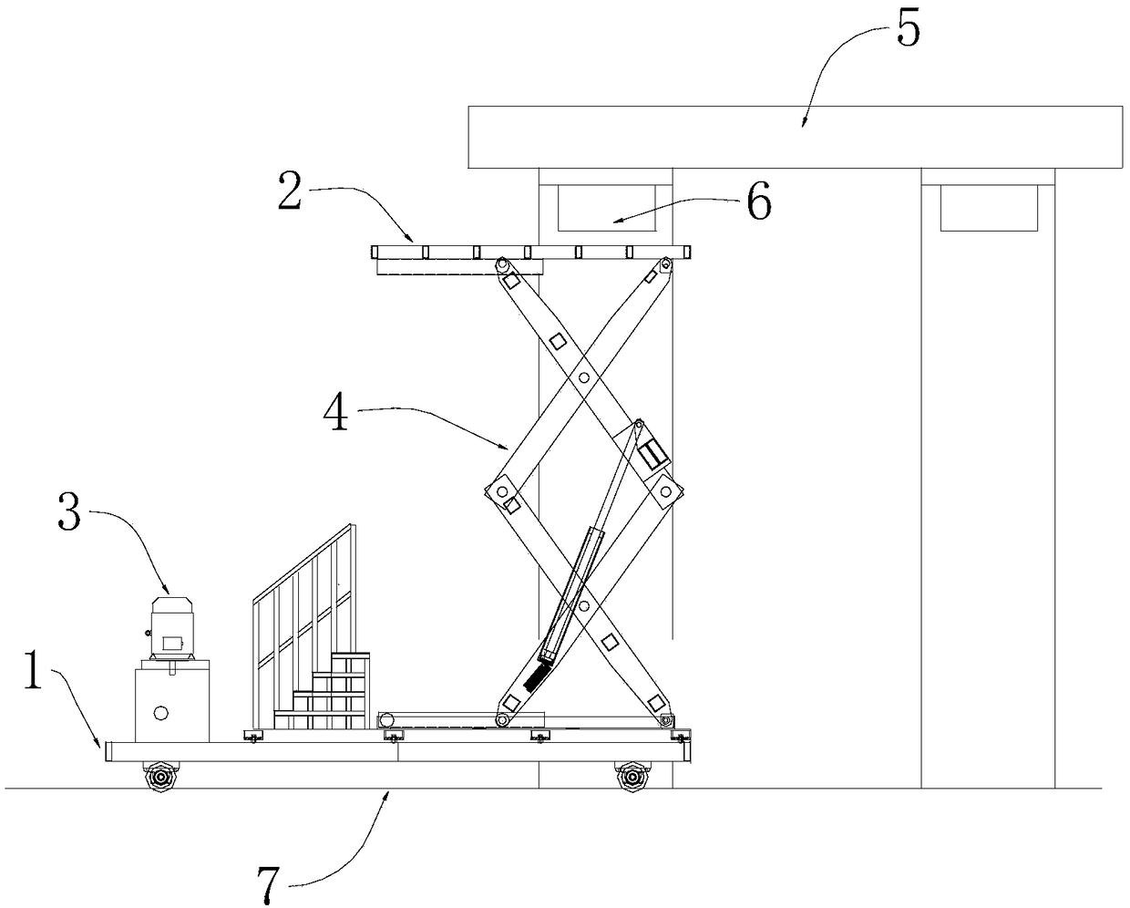
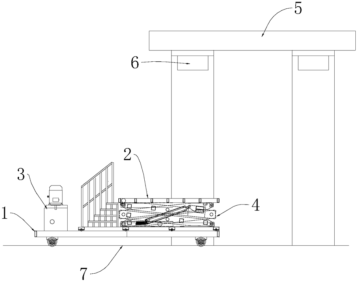
The invention provides a rolling mill pressure head auxiliary dismounting and mounting device and a pressure head dismounting method. The rolling mill pressure head auxiliary dismounting and mountingdevice comprises a rail flat car, a lifting operation platform, a main controller and a remote controller; the lifting operation platform is detachably arranged on the rail flat car; the main controller is arranged on the rail flat car; a traveling drive mechanism of the rail flat car and a lifting drive mechanism of the lifting operation platform are connected with the main controller; the remotecontroller is in wireless connection with the main controller; and when the remote controller sends an action instruction to the main controller, the traveling drive mechanism and the lifting drive mechanism are controlled by the main controller to operate or stop. The rolling mill pressure head auxiliary dismounting and mounting device and the pressure head dismounting method can make a single worker enter a rolling mill and rapidly dismount or mount a pressure head of a pressing device inside the rolling mill, the dismounting, mounting and maintaining efficiency of the pressure head is improved, and safety of dismounting and mounting of the pressure head is improved.

Description

technical field [0001] The invention relates to rolling mill overhaul technology, in particular to an auxiliary dismounting device for a rolling mill pressure head and a method for disassembling the pressure head. Background technique [0002] The roughing mill is one of the main equipments of the hot-rolled sheet and strip production line, and the rolling mill pressing device is the key equipment for rolling the slab in the roughing mill. When the pressing device of the rolling mill breaks down, the rolling line must be shut down and the pressure head of the pressing device must be removed for inspection and replacement. Put the pressure head on the support roller, remove the flange bolts of the pressure head and the oil return pipe, then lift up the screw rod, pull out the support roller, and finally lift the pressure head to the ground for inspection and assembly by a crane. After the pressure head is assembled Lifted to the backup rolls and pushed into the rolling mill ...

Claims


Application Information

Patent Timeline
Patent Type & Authority Applications(China)
IPC IPC(8): B23P19/00B66F11/00B66F11/04
CPCB23P19/00B66F11/00B66F11/04
Inventor 李宏亮董辉任晓杰赵夏荣
Owner MCC BAOSTEEL TECH SERVICE
Why Eureka
Try Eureka