Oil supply device

An oil supply device and oil tank technology, applied in mechanical equipment, engine components, engine lubrication, etc., can solve problems such as troublesome operation, and achieve the effects of simple and convenient operation, energy saving and waste prevention.

Inactive Publication Date: 2018-10-09
重庆合聚达智能装备有限公司
View PDF1 Cites 8 Cited by
  • Summary
  • Abstract
  • Description
  • Claims
  • Application Information

AI Technical Summary

Problems solved by technology

At present, the method of applying lubricating oil on sprockets and chains is usually manual oiling, which is troublesome to operate

Method used


Image

  • Oil supply device

Examples


Embodiment Construction

[0017] The following is further described in detail through specific implementation methods:

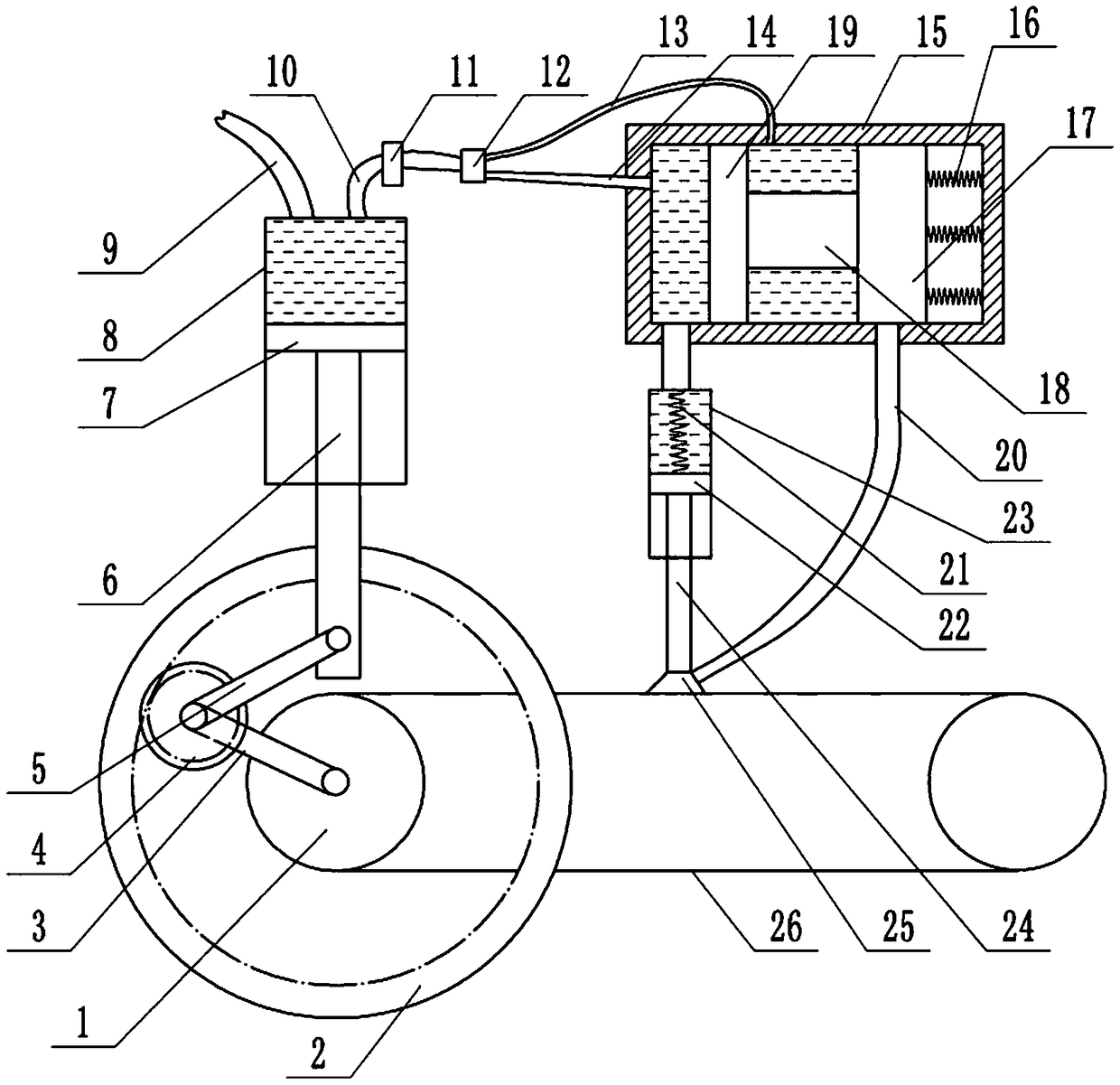
[0018] The reference signs in the accompanying drawings include: sprocket 1, ring gear 2, first connecting rod 3, gear 4, second connecting rod 5, first piston rod 6, first piston 7, first piston cylinder 8 , oil inlet pipe 9, oil outlet pipe 10, second one-way valve 11, three-way pipe 12, second through pipe 13, first through pipe 14, housing 15, compression spring 16, second slider 17, coupling shaft 18 , the first slider 19, the third pipe 20, the extension spring 21, the second piston 22, the second piston cylinder 23, the second piston rod 24, the brush 25, the chain 26.

[0019] The embodiment is basically as attached figure 1 Shown: an oil supply device, including a frame, the frame is provided with a fuel tank (not shown), a first piston mechanism and a drive mechanism.

[0020] The first piston mechanism comprises a first piston cylinder 8, a first piston 7 and a first pis...


PUM


Abstract

The invention relates to an oil supply device which comprises a machine frame. The machine frame is provided with an oil tank, a first piston mechanism and a driving mechanism. The first piston mechanism comprises a first piston cylinder, a first piston and a first piston rod. The first piston is in sealed sliding connection with the interior of the first piston cylinder, the first piston rod is fixedly connected to the first piston, an oil inlet pipe is connected between the first piston cylinder and the oil tank, the oil inlet pipe is provided with a first one-way valve, the first piston cylinder is connected with an oil drainage mechanism, a brush is connected to the oil drainage mechanism, and the oil drainage mechanism is provided with a second one-way valve. The driving mechanism comprises an inner gear ring and a gear, the gear is engaged with the inner gear ring, a first connection rod is fixedly connected to the gear, the end, away from the gear, of the first connection rod isused for being detachably connected with a chain wheel, a second connection rod is fixedly connected to the gear, and the end, away from the gear, of the second connection rod is rotationally connected to the first piston rod. By means of the scheme, a chain is automatically coated with oil.

Description

technical field [0001] The invention relates to the field of machinery, in particular to an oil supply device. Background technique [0002] The sprocket and chain mechanism is a common power transmission mechanism, and the power transmission is realized through the engagement of the sprocket and the chain. In order to ensure the stability and smoothness of the meshing of the chain and the sprocket, lubricating oil is usually applied to the sprocket and the chain to lubricate the sprocket and the chain, and the lubricating oil is applied to the sprocket and the chain to lubricate Oil can also play a role in cooling, preventing the sprocket and chain from being too high in temperature, which is beneficial to improving the life of the sprocket and chain and reducing the wear between the sprocket and the chain. Now at present, the mode of smearing lubricating oil on the sprocket wheel and chain is usually manual oiling, and the operation is cumbersome. Therefore, designing a ...

Claims


Application Information

Patent Timeline
Patent Type & Authority Applications(China)
IPC IPC(8): F16N7/18F16N7/24
CPCF16N7/18F16N7/24
Inventor 姚强
Owner 重庆合聚达智能装备有限公司
Why Eureka
Try Eureka