Driving substrate and display panel

A technology for driving substrates and driving areas, which can be applied to static indicators, instruments, semiconductor devices, etc., and can solve problems such as different brightness

Active Publication Date: 2018-10-09
KUNSHAN GO VISIONOX OPTO ELECTRONICS CO LTD
View PDF5 Cites 14 Cited by
  • Summary
  • Abstract
  • Description
  • Claims
  • Application Information

AI Technical Summary

Problems solved by technology

[0004] Based on this, it is necessary to provide a driving substrate and a display panel for the problem that the brightness of the special-shaped display area of ​​the screen body is different from that of the normal display area.

Method used


Image

  • Driving substrate and display panel
  • Driving substrate and display panel

Examples


Embodiment Construction

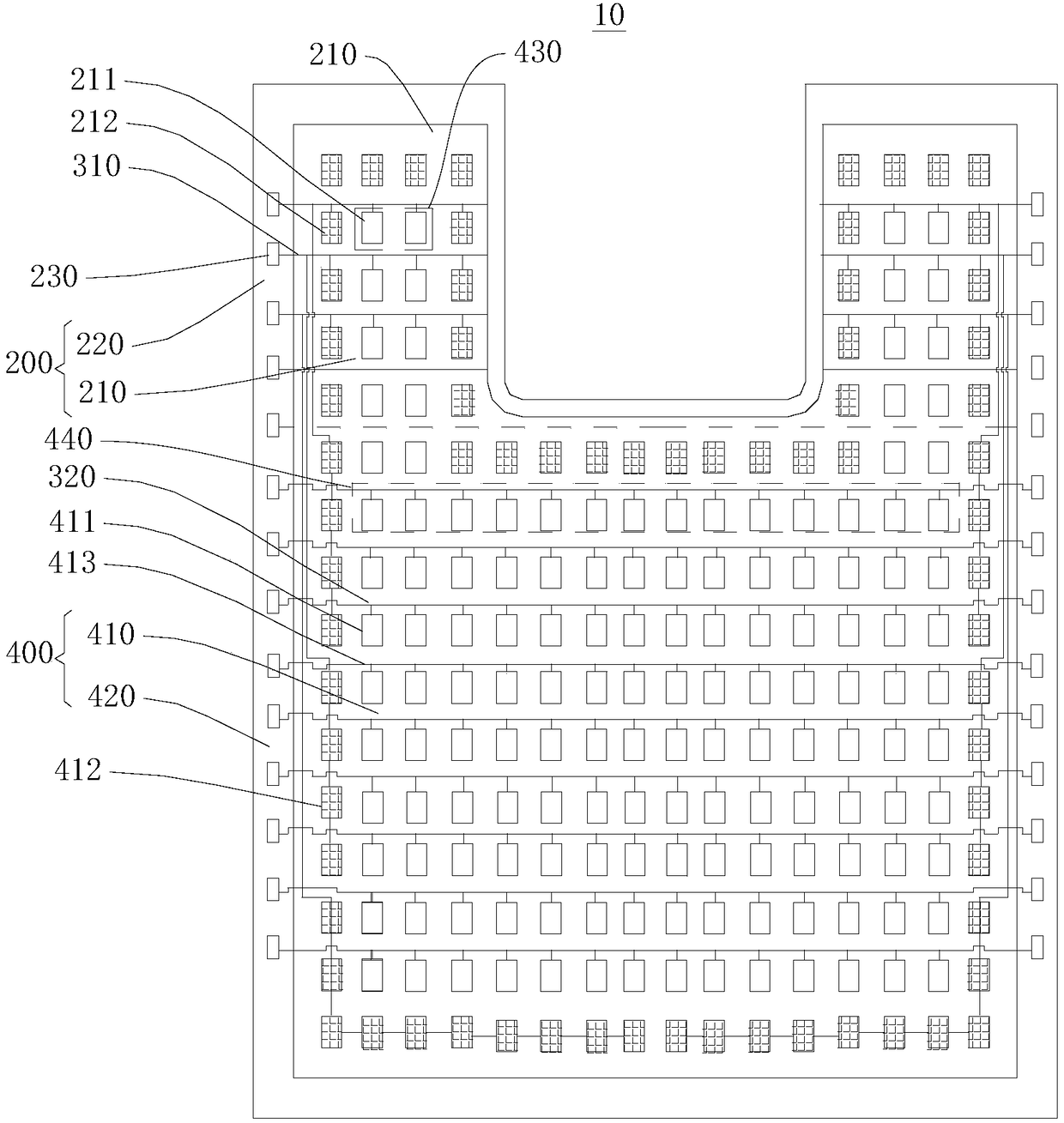
[0059] See figure 1 , the present application provides a driving substrate 10 . The driving substrate 10 includes a base 100 , a plurality of first pixel driving unit rows 430 , a plurality of first signal lines 310 and a plurality of first dummy pixel driving units 212 . The substrate 100 includes a profiled driving region 200 . The shaped driving region 200 includes a shaped display driving region 210 and a shaped non-display driving region 220 . The first row of pixel driving units 430 is located in the special-shaped display driving region 210 . The first pixel driving unit row 430 includes a plurality of first pixel driving units 211 . The first pixel driving unit 211 is disposed on the substrate 100 . The first signal line 310 is disposed on the substrate 100 . Each first signal line 310 is used to electrically connect the plurality of first pixel driving units 211 in one row 430 of the first pixel driving units. The first dummy pixel driving unit 212 is located in...


PUM


Abstract

The invention relates to a driving substrate and a display panel. The substrate comprises a special-shaped driving region; the special-shaped driving region comprises a special-shaped display drivingregion and a special-shaped non-display driving region; multiple first pixel driving units are positioned in the special-shaped display driving region, and the multiple first pixel driving units are arranged on the substrate; multiple first signal lines are arranged on the substrate; each first signal line is used for being electrically connected to multiple first pixel driving units in one firstpixel driving unit line; multiple first virtual pixel driving units are arranged around the edge of the special-shaped display driving region; the first signal lines are electrically connected with multiple first pixel driving units in one first pixel driving unit line through at least one first virtual pixel driving unit; and the first signal lines are connected with at least one first virtual pixel driving unit and then connected with at least one first pixel driving unit in series, so that load of the first signal lines can be improved.

Description

technical field [0001] The present application relates to the display field, in particular to a driving substrate and a display panel. Background technique [0002] With the continuous development of the mobile phone industry, the screen body of a full-screen mobile phone has the advantages of a large screen-to-body ratio and a narrow frame, which greatly improves the visual effect of the viewer and has attracted widespread attention. [0003] In the production process of the full screen, the special-shaped display area is usually formed by special-shaped designs such as slots on the screen body. The number of pixels at the slot is less than the number of pixels in the normal display area. Therefore, the load of the pixel driving signal in the special-shaped display area is very different from that of the normal display area, resulting in different RC delays of driving signals such as pixel scanning, resulting in different brightness between the special-shaped display area ...

Claims


Application Information

Patent Timeline
Patent Type & Authority Applications(China)
IPC IPC(8): H01L27/32G09G3/3225
CPCG09G3/3225H10K59/122H10K59/121
Inventor 马宏帅孙光远张九占韩珍珍朱晖
Owner KUNSHAN GO VISIONOX OPTO ELECTRONICS CO LTD
Why Eureka
Try Eureka