A Harmonic Elimination Method of Ferromagnetic Resonance

A ferromagnetic resonance and harmonic elimination technology, which is applied in the direction of emergency protection circuit devices, electrical components, and emergency protection circuit devices for limiting overcurrent/overvoltage, can solve the problem of increasing the cost of harmonic elimination, failure of harmonic elimination, and inability to Realize problems such as fast harmonic elimination, achieve the effect of improving the efficiency of harmonic elimination, quickly eliminating, and preventing frequent actions

Active Publication Date: 2020-06-02
YUNNAN POWER GRID CO LTD ELECTRIC POWER RES INST
View PDF4 Cites 0 Cited by
  • Summary
  • Abstract
  • Description
  • Claims
  • Application Information

AI Technical Summary

Problems solved by technology

[0004] However, the method of installing a resonance eliminator at the primary center point of the electromagnetic voltage transformer can prevent the ferromagnetic resonance between the three-phase voltage and the ground that is easily generated in the system, but for the power frequency resonance caused by disconnection The effect is poor, and it is easy to cause the voltage increase of the neutral point of the electromagnetic voltage transformer, the insulation breakdown of the end of the electromagnetic voltage transformer and other undesirable phenomena, causing the resonance eliminator to lose its function; adding a damping resistor will cause heat due to the damping resistor Affect the resonance elimination effect; it is difficult to distinguish the power frequency resonance by using the secondary resonance elimination device of the microcomputer to detect the zero-sequence voltage and the three-phase voltage waveform, and the resonance elimination speed of this method is slow, and it cannot achieve fast resonance elimination, and it is easy to appear due to resonance Insufficient loop damping and failure of harmonic elimination
[0005] Therefore, adopting the above-mentioned existing harmonic elimination method will not only prolong the harmonic elimination time and increase the harmonic elimination cost, but also greatly affect the harmonic elimination efficiency, cause frequent damage to equipment, and pose a serious threat to the safe and stable operation of the power grid and equipment

Method used


Image

  • A Harmonic Elimination Method of Ferromagnetic Resonance
  • A Harmonic Elimination Method of Ferromagnetic Resonance
  • A Harmonic Elimination Method of Ferromagnetic Resonance

Examples


Embodiment Construction

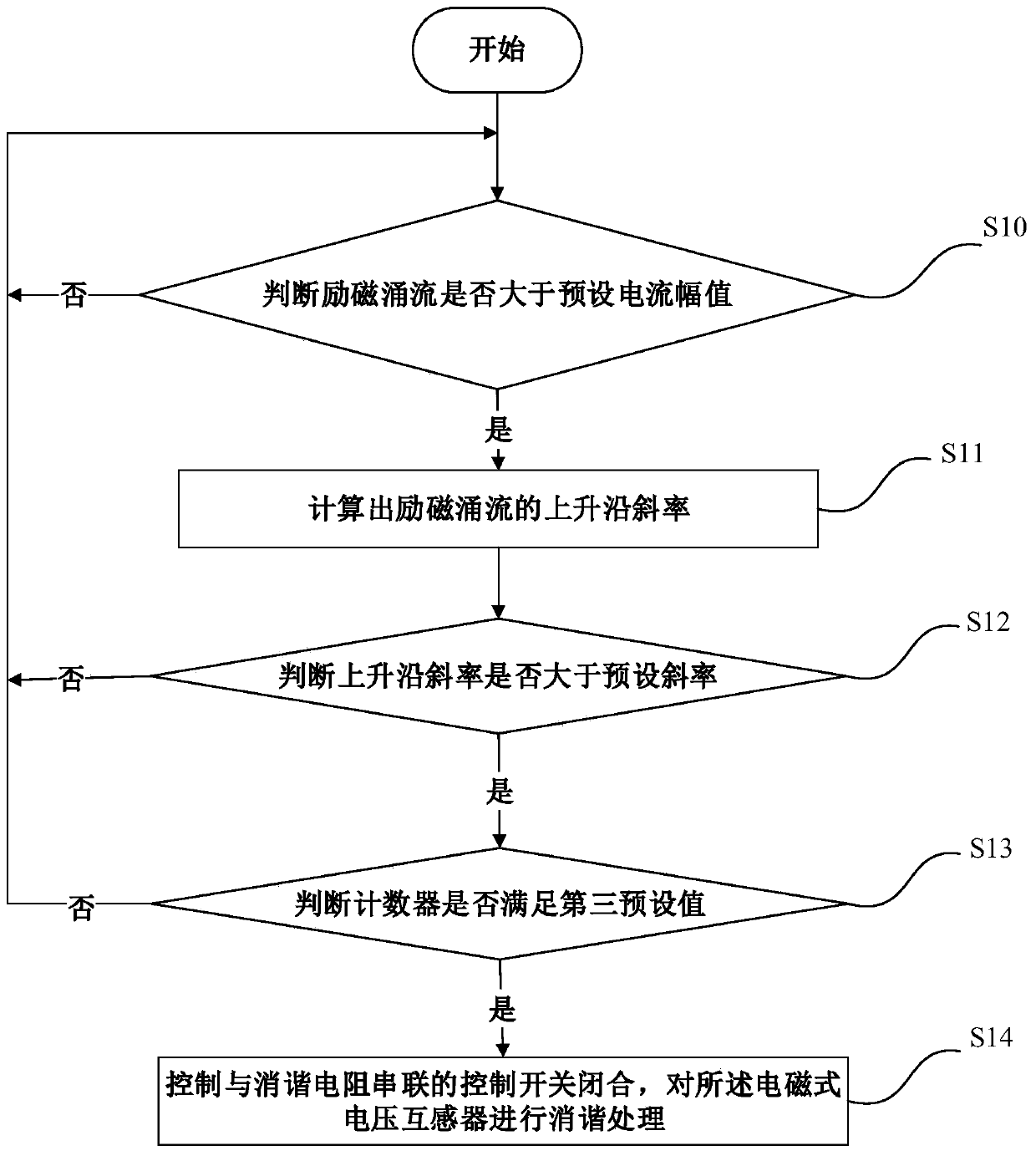
[0032] The technical solutions in the embodiments of the present application are clearly and completely described below in conjunction with the accompanying drawings in the present application. Obviously, the described embodiments are only part of the embodiments of the present application, not all of the embodiments. Based on the embodiments in this application, all other embodiments obtained by persons of ordinary skill in the art without making creative efforts fall within the protection scope of the present invention.

[0033] In the following description, a lot of specific details are set forth in order to fully understand the present invention, but the present invention can also be implemented in other ways that are different from the description again, and those skilled in the art can do similar By extension, the present invention is therefore not limited to the specific examples disclosed below.

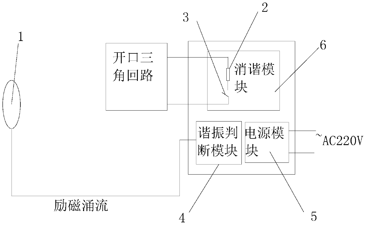
[0034] image 3 It is a structural schematic diagram of a ferromagnetic...


PUM


Abstract

The invention provides a resonance elimination method for ferromagnetic resonance. The method comprises the following steps of judging whether a excitation surge current exceeds a preset current amplitude or not; and if yes, further calculating a rising edge slope of the excitation surge current; comparing the rising edge slope of the excitation surge current with a preset slope, and when the rising edge slope of the excitation surge current is larger than the preset slope, showing that an electromagnetic voltage transformer generates the ferromagnetic resonance; and finally, comparing a counter with a third preset value, if the counter meets the third preset value, closing a control switch, and making a resonance elimination device carry out resonance elimination processing on the electromagnetic voltage transformer. According to the resonance elimination method for the ferromagnetic resonance, a resonance elimination resistor is directly connected to an open-delta loop, and the ferromagnetic resonance can be accurately and rapidly eliminated, so that the resonance elimination efficiency of the ferromagnetic resonance is effectively improved. The amplitude and the rising edge slope of the excitation surge current are adopted as conditions for distinguishing the ferromagnetic resonance and other abnormal states, so that the resonance elimination device is prevented from frequent actions.

Description

technical field [0001] The present application relates to the technical field of power system safety prevention and control, in particular to a ferromagnetic resonance harmonic elimination method. Background technique [0002] In the 6-35kV power distribution network, the neutral point of the system is not grounded, and the busbar is connected with an electromagnetic voltage transformer (Potential Transformer, PT) that is insulated from the ground in the measurement and monitoring system. When the busbar switch is closed, it operates 1. When the single-phase arc light grounding automatically disappears in the line or the system load changes drastically, the transient impact process generated will excite ferromagnetic resonance between the PT and the three-phase wire-to-ground capacitance, resulting in system overvoltage and PT. Overcurrent causes the weak insulation equipment in the system to flash over to the ground and the high-voltage fuse of the PT blows, or even burns t...

Claims


Application Information

Patent Timeline
Patent Type & Authority Patents(China)
IPC IPC(8): H02H9/00H02H9/02
CPCH02H9/007H02H9/028
Inventor 李昊刘红文王科桑前浩
Owner YUNNAN POWER GRID CO LTD ELECTRIC POWER RES INST
Why Eureka
Try Eureka